Formation Of Propeller Blades And Their Geometric Features In Section
Formation Of Propeller Blades And Their Geometric Features In Section
| Since the propeller is a free-form surface part, its shape is complicated. To plan the machining plan of the propeller, we must first analyze its geometric characteristics. |
Since the marine propeller is a free-form surface part, its shape is complicated. To plan the machining plan of the propeller, we must first analyze its geometric characteristics. The original propellers, like screws, consisted of one or two turns around the shaft. Later operation found that if a section of the spiral surface is taken instead of the full circle, the efficiency will increase. It took more than 100 years of production practice to form this shape today. The main design method of the propeller is the map method, that is, the design is performed by means of the map drawn according to the experimental results of the propeller model. According to the design map, the machining propellers are mainly B-type propellers, AU-type propellers, and SSPA-type propellers.
Formation Of Propeller Blades
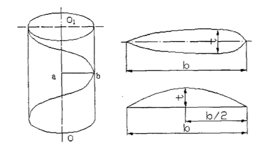
The pressure surface of the propeller blade is part of the spiral surface. The spiral surface is formed by the bus bar ab rotating around the axis OO1 of the propeller hub, and at the same time moving upward along OO1 at a constant speed, as shown in FIG. 1. The locus of motion of any point on the generatric line is a spiral.
When viewed in the direction of the axis, the spiral is an arc. When viewed from the direction perpendicular to the axis, the spiral is a sinusoid.
The distance between any point on the same helix and the fixed axis OO1 is constant. Therefore, if a cylindrical surface is made with the radius of the spiral as the radius (the cylindrical centerline is the axis OO1), the spiral is included in the cylindrical surface. The backward tilt of the busbar is called backward tilt, which is expressed by the backward tilt angle ε, generally ε = 5 ~ 15 °.
Section Characteristics Of The Blade
Because the blades must withstand the thrust of the propeller, they must have a certain thickness. The blades have a maximum thickness on the cut surface at different radii, which is determined through light calculations.
A cylindrical surface with a radius R (the center of which coincides with the center of the propeller shaft) is tangent to the blade, and the cut section is the blade cut surface. Looking in the direction of the feather axis, the cut plane is a part of an arc with a radius R, and is not a straight line.
There are generally two types of blade sections: airfoil and bow, as shown in Figure 2. The distance b between the two ends of the tangent plane is called the chord width of the tangent plane, which is also called the chord length of the tangent plane. The maximum thickness of the section is represented by t.
The maximum thickness of the arch-shaped section is in the middle, that is, b / 2. The maximum thickness of the airfoil section is about a third of the chord width from the leading edge, that is, about b / 3. The position of the maximum thickness of each section of the blade is not constant.
The ratio of the maximum thickness to the chord width is called the thickness ratio, and it is expressed by δ, that is, δ = t / b. δ indicates the degree of fatness and thinness of the section, and large δ indicates that the section is thick and narrow
Link to this article: Formation Of Propeller Blades And Their Geometric Features In Section
Reprint Statement: If there are no special instructions, all articles on this site are original. Please indicate the source for reprinting:https://www.cncmachiningptj.com/,thanks!
 PTJ® provides a full range of Custom Precision cnc machining china services.ISO 9001:2015 &AS-9100 certified. 3, 4 and 5-axis rapid precision CNC machining services including milling, turning to customer specifications,Capable of metal & plastic machined parts with +/-0.005 mm tolerance.Secondary services include CNC and conventional grinding, drilling,die casting,sheet metal and stamping.Providing prototypes, full production runs, technical support and full inspection.Serves the automotive, aerospace, mold&fixture,led lighting,medical,bicycle, and consumer electronics industries. On-time delivery.Tell us a little about your project’s budget and expected delivery time. We will strategize with you to provide the most cost-effective services to help you reach your target,Welcome to Contact us ( [email protected] ) directly for your new project.
- 5 Axis Machining
- Cnc Milling
- Cnc Turning
- Machining Industries
- Machining Process
- Surface Treatment
- Metal Machining
- Plastic Machining
- Powder Metallurgy Mold
- Die Casting
- Parts Gallery
- Auto Metal Parts
- Machinery Parts
- LED Heatsink
- Building Parts
- Mobile Parts
- Medical Parts
- Electronic Parts
- Tailored Machining
- Bicycle Parts
- Aluminum Machining
- Titanium Machining
- Stainless Steel Machining
- Copper Machining
- Brass Machining
- Super Alloy Machining
- Peek Machining
- UHMW Machining
- Unilate Machining
- PA6 Machining
- PPS Machining
- Teflon Machining
- Inconel Machining
- Tool Steel Machining
- More Material

