Research on Error Inversion Identification and Physical-Driven Path Optimization System for CNC Machining of Complex Titanium Alloy Multi-Dimensional Free-Form Surfaces
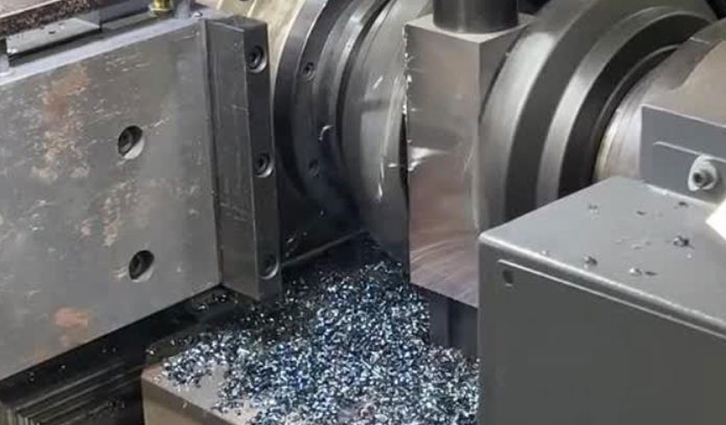
The machining of complex titanium alloy multi-dimensional free-form surfaces represents a pinnacle of modern manufacturing technology, particularly in industries such as aerospace, biomedical engineering, and automotive, where precision, reliability, and material properties are paramount. Titanium alloys, renowned for their high strength-to-weight ratio, corrosion resistance, and thermal stability, pose significant challenges in computer numerical control (CNC) machining due to their poor machinability, high cutting forces, and propensity for tool wear. The complexity of free-form surfaces—characterized by non-linear, non-planar geometries—further exacerbates these challenges, necessitating advanced strategies for error identification and tool path optimization.
Error inversion identification and physical-driven path optimization systems have emerged as critical methodologies to enhance the accuracy and efficiency of CNC machining processes for such surfaces. Error inversion identification involves modeling and compensating for geometric, kinematic, thermal, and tool deflection errors that affect machining precision. Physical-driven path optimization, on the other hand, leverages physical principles, material properties, and machine dynamics to generate tool paths that minimize machining time, reduce energy consumption, and improve surface quality. These approaches are particularly vital for titanium alloys, where suboptimal machining conditions can lead to poor surface integrity, dimensional inaccuracies, and accelerated tool degradation.
This article provides a comprehensive review of the state-of-the-art research on error inversion identification and physical-driven path optimization for CNC machining of complex titanium alloy free-form surfaces. It explores the theoretical foundations, methodologies, experimental validations, and emerging trends in this field, with a focus on achieving high precision and efficiency. The article is structured into several sections, each addressing a specific aspect of the research, supported by detailed tables for comparative analysis.
Background and Significance
Titanium Alloys in Advanced Manufacturing
Titanium alloys, such as Ti-6Al-4V and TC21, are widely used in high-performance applications due to their exceptional mechanical properties. Ti-6Al-4V, a two-phase (α+β) alloy, is the most commonly used titanium alloy, accounting for approximately 50% of global titanium production. Its high strength, low density, and excellent corrosion resistance make it ideal for aerospace components like turbine blades, airframes, and biomedical implants. However, its low thermal conductivity (approximately 6.7 W/m·K compared to 43 W/m·K for steel) leads to high cutting temperatures, which accelerate tool wear and compromise surface integrity. TC21, a newer high-strength alloy (Ti-6Al-3Mo-2Nb-2Sn-2Zr-1.5Cr), offers improved toughness but poses similar machining challenges.
The machining of titanium alloys is inherently difficult due to their high chemical reactivity, which causes adhesion to cutting tools, and their low elastic modulus, which results in significant tool deflection. These properties necessitate precise control of machining parameters, such as cutting speed, feed rate, and depth of cut, to achieve desired outcomes.
Free-Form Surfaces and CNC Machining
Free-form surfaces, also known as sculptured surfaces, are defined by complex, non-analytical geometries that cannot be described by simple equations like planes or cylinders. These surfaces are typically represented using Non-Uniform Rational B-Splines (NURBS) or point cloud data in modern CAD/CAM systems. In industries like aerospace, free-form surfaces are prevalent in components such as turbine blades, impellers, and aerodynamic fairings, where dimensional accuracy and surface finish are critical.
CNC machining, particularly multi-axis (3- to 5-axis) milling, is the primary method for manufacturing free-form surfaces. Multi-axis CNC systems allow for greater flexibility in tool orientation and path planning, enabling the machining of complex geometries. However, the increased degrees of freedom introduce additional sources of error, including kinematic errors (due to machine axis misalignments), geometric errors (from imperfect machine components), thermal errors (from heat generation), and tool deflection errors (from cutting forces).
Challenges in Machining Titanium Alloy Free-Form Surfaces
The combination of titanium alloys and free-form surfaces presents unique challenges:
-
High Cutting Forces and Tool Wear: Titanium alloys generate high cutting forces, leading to rapid tool wear and potential tool failure. For example, cutting forces in milling Ti-6Al-4V can exceed 1000 N, significantly higher than for aluminum alloys.
-
Thermal Effects: The low thermal conductivity of titanium alloys causes heat to concentrate at the tool-workpiece interface, with temperatures reaching up to 1000°C, degrading tool life and surface quality.
-
Geometric Complexity: Free-form surfaces require intricate tool paths, increasing the likelihood of errors due to tool path deviations, gouging, or overcutting.
-
Error Accumulation: Multi-axis machining introduces cumulative errors from multiple sources, including machine kinematics, tool deflection, and thermal deformation.
-
Surface Integrity: Poor machining conditions can lead to surface defects, such as micro-cracks, residual stresses, or poor surface roughness (Ra > 0.8 μm), which are unacceptable for critical applications.
To address these challenges, researchers have developed error inversion identification and physical-driven path optimization systems, which are discussed in detail in the following sections.
Error Inversion Identification in CNC Machining
Overview of Error Inversion Identification
Error inversion identification is a methodology that models and compensates for errors in CNC machining by analyzing the discrepancies between the nominal (intended) and actual tool paths. The goal is to identify the sources of error, quantify their impact, and apply corrective measures to achieve the desired machining accuracy. This process is particularly critical for titanium alloy free-form surfaces, where even small deviations (e.g., 10 μm) can lead to significant functional issues in the final component.
The error inversion process typically involves three steps:
-
Error Modeling: Developing mathematical models to describe geometric, kinematic, thermal, and tool deflection errors.
-
Error Identification: Measuring or estimating errors using sensors, laser interferometers, or simulation tools.
-
Error Compensation: Modifying tool paths or machine parameters to mitigate identified errors.
Types of Errors in CNC Machining
Errors in CNC machining can be broadly categorized into the following types, each requiring specific identification and compensation strategies:
Geometric Errors
Geometric errors arise from imperfections in the machine tool's components, such as linear axes, rotary axes, and spindles. For a 5-axis CNC machine, there are typically 41 geometric error parameters, including 21 translational errors (e.g., positioning errors) and 20 angular errors (e.g., tilt errors). These errors cause deviations in the tool's position relative to the workpiece, affecting dimensional accuracy.
Table 1: Common Geometric Errors in 5-Axis CNC Machining
|
Error Type |
Description |
Typical Magnitude (μm or °) |
Compensation Method |
|---|---|---|---|
|
Linear Positioning Error |
Deviation in axis movement along X, Y, Z |
5–20 μm |
Kinematic transformation, NC code modification |
|
Angular Error |
Misalignment of rotary axes (A, B, C) |
0.01–0.05° |
Screw theory-based correction |
|
Squareness Error |
Non-orthogonality between axes |
0.02–0.1° |
Calibration with laser interferometer |
|
Backlash Error |
Play in mechanical components |
10–50 μm |
Pre-compensation in NC program |
Source: Adapted from,
Kinematic Errors
Kinematic errors result from inaccuracies in the coordinated motion of multiple axes in a CNC machine. In 5-axis machining, kinematic errors are particularly significant due to the complex interplay of linear and rotary axes. For example, a misalignment in the rotary axis can cause a tool to deviate from its intended path, leading to contour errors.
Thermal Errors
Thermal errors occur due to heat generation during machining, particularly in titanium alloys, where high cutting temperatures are common. Thermal deformation of the spindle, workpiece, or machine structure can cause dimensional inaccuracies. For instance, spindle thermal expansion can result in a positional error of up to 50 μm after prolonged machining.
Tool Deflection Errors
Tool deflection errors are caused by cutting forces bending the tool, especially during the machining of hard materials like titanium alloys. These errors are more pronounced in free-form surface machining, where the tool-workpiece contact area varies continuously, leading to fluctuating forces.
Error Modeling Techniques
Error modeling is the foundation of error inversion identification. Several techniques have been developed to model errors in CNC machining:
-
Homogeneous Transformation Matrix (HTM): HTM models the kinematic chain of a multi-axis machine, mapping nominal tool positions to actual positions while accounting for geometric and kinematic errors. This method is widely used for its mathematical rigor and ability to handle complex machine configurations.
-
Screw Theory: Screw theory provides a unified framework for modeling both translational and rotational errors in multi-axis systems. It is particularly effective for 5-axis machines, where rotary axes introduce complex error interactions.
-
Finite Element Analysis (FEA): FEA is used to model thermal and tool deflection errors by simulating the physical behavior of the machine and workpiece under cutting forces and heat loads.
-
Machine Learning (ML): ML-based models, such as artificial neural networks (ANNs) and relevance vector machines (RVMs), predict errors based on historical machining data and sensor inputs. These models are particularly useful for capturing non-linear and time-varying errors.
Error Identification Methods
Identifying errors requires precise measurement or estimation techniques. Common methods include:
-
Laser Interferometry: Laser interferometers measure linear and angular errors with high accuracy (e.g., ±0.5 μm/m for linear errors). They are widely used for calibrating geometric errors in CNC machines.
-
Ball Bar Testing: Ball bar tests assess kinematic errors by measuring deviations in circular tool paths, identifying errors in axis synchronization.
-
On-Machine Measurement (OMM): OMM systems use touch-trigger probes mounted on the machine spindle to measure machined surfaces in real-time, enabling error detection without removing the workpiece.
-
Data-Driven Approaches: Machine learning algorithms, such as deep separable convolutional gated recurrent networks (DSCGRN), analyze multi-sensor data to identify error patterns and predict tool wear or degradation states,.
Error Compensation Strategies
Once errors are identified, compensation strategies are applied to correct tool paths or machine parameters:
-
NC Code Modification: Modifying the numerical control (NC) code to adjust tool positions based on the error model. This pre-compensation approach is effective for geometric and kinematic errors,.
-
Real-Time Compensation: Using digital I/O interfaces to communicate with the CNC controller and adjust tool paths in real-time. This method is less common due to the complexity of commercial CNC controllers.
-
Inverse Dynamics Compensation: Modifying the commanded tool path to account for inertia and damping effects, often using Pythagorean-hodograph curves to achieve zero contour error for specific controllers.
-
Thermal Error Compensation: Implementing thermal sensors to monitor spindle temperature and applying compensation models to correct for thermal expansion.
Table 2: Comparison of Error Compensation Methods
|
Method |
Applicability |
Advantages |
Limitations |
Reference |
|---|---|---|---|---|
|
NC Code Modification |
Geometric, Kinematic Errors |
Cost-effective, widely applicable |
Requires accurate error model |
, |
|
Real-Time Compensation |
Dynamic Errors |
High precision, adaptive |
Complex implementation, controller access issues |
|
|
Inverse Dynamics |
Contour Errors |
Zero contour error for P controllers |
Limited to specific controllers |
|
|
Thermal Compensation |
Thermal Errors |
Improves long-term accuracy |
Requires extensive sensor setup |
|
Case Studies in Error Inversion Identification
Several studies have demonstrated the efficacy of error inversion identification for titanium alloy free-form surfaces:
-
Tian et al. (2025): Developed a universal geometric error model for 5-axis CNC machines using screw theory, achieving a 50% reduction in form error for flat surfaces by compensating for geometric errors.
-
Outeiro (2025): Applied a machine learning-based model to predict residual stresses in orthogonal cutting of Ti-6Al-4V, optimizing rake angle and cutting speed to increase compressive residual stresses by 40%.
-
Hsu et al. (2012): Used OMM with touch-trigger probes to detect and compensate for machining errors in 5-axis flank milling of thin-walled titanium parts, reducing dimensional errors from 30 mm to below 4 mm.
These case studies highlight the importance of integrating advanced modeling and measurement techniques to achieve high precision in titanium alloy machining.
Physical-Driven Path Optimization
Overview of Physical-Driven Path Optimization
Physical-driven path optimization focuses on generating tool paths that account for the physical properties of the material, machine dynamics, and cutting conditions to maximize efficiency and quality. Unlike traditional tool path generation, which prioritizes geometric constraints like scallop height, physical-driven approaches incorporate material removal mechanics, cutting forces, thermal effects, and machine kinematics to optimize machining outcomes.
For titanium alloy free-form surfaces, physical-driven path optimization aims to:
-
Minimize machining time and energy consumption.
-
Reduce tool wear and cutting forces.
-
Enhance surface finish and dimensional accuracy.
-
Prevent chatter and vibrations that degrade surface quality.
Principles of Physical-Driven Path Optimization
Physical-driven path optimization relies on several key principles:
-
Material Removal Mechanics: Understanding the interaction between the tool and workpiece, including chip formation, cutting forces, and heat generation.
-
Machine Dynamics: Accounting for the kinematic and dynamic constraints of the CNC machine, such as spindle speed, feed rate, and axis acceleration limits.
-
Surface Integrity: Optimizing parameters to achieve desired surface roughness (Ra < 0.4 μm) and compressive residual stresses for improved fatigue life.
-
Multi-Objective Optimization: Balancing conflicting objectives, such as minimizing machining time while maintaining surface quality, using techniques like genetic algorithms (GAs) or response surface methodology (RSM).
Tool Path Generation Strategies
Several tool path generation strategies have been developed for free-form surface machining, each with specific advantages for titanium alloys:
-
Iso-Scallop Tool Paths: Maintain constant scallop height to ensure uniform surface finish. These paths reduce total path length by 22–50% compared to traditional iso-parametric paths.
-
Contour-Parallel Tool Paths: Follow the surface contours to minimize tool retractions and improve machining efficiency. These paths are effective for complex surfaces with varying curvature.
-
Zig-Zag Tool Paths: Simple and widely used, but less efficient for free-form surfaces due to frequent direction changes that increase machining time.
-
NURBS-Based Interpolation: Uses NURBS curves to generate smooth tool paths, maintaining constant cutter contact (CC) velocity and reducing micro-geometrical defects,.
-
Adaptive Tool Paths: Adjust path intervals based on surface curvature and error tolerances, improving efficiency and accuracy for complex geometries,.
Table 3: Comparison of Tool Path Generation Strategies
|
Strategy |
Description |
Advantages |
Limitations |
Reference |
|---|---|---|---|---|
|
Iso-Scallop |
Constant scallop height |
Uniform surface finish, reduced path length |
Computationally intensive |
|
|
Contour-Parallel |
Follows surface contours |
Fewer retractions, efficient |
Limited to specific geometries |
|
|
Zig-Zag |
Alternating linear paths |
Simple implementation |
Inefficient for complex surfaces |
|
|
NURBS-Based |
Smooth paths using NURBS curves |
Constant CC velocity, high quality |
Requires advanced CAM systems |
, |
|
Adaptive |
Adjusts paths based on curvature |
High efficiency, adaptive to geometry |
Complex algorithm development |
, |
Optimization Techniques
Optimization techniques are critical for determining the best machining parameters and tool paths. Common methods include:
-
Genetic Algorithms (GAs): GAs are used to optimize tool paths by evaluating multiple criteria, such as surface deviation and machining time. For example, a study optimized three 3-axis tool paths (Optimized-Z, Raster, 3D-Offset) for titanium alloy surfaces, achieving a Pareto-optimal solution for quality and productivity.
-
Response Surface Methodology (RSM): RSM develops predictive models for machining outcomes (e.g., surface roughness, cutting temperature) based on experimental data. A study on Ti-6Al-4V turning achieved a 27% reduction in cutting temperature using RSM.
-
Taguchi Method: The Taguchi method uses orthogonal arrays to minimize experimental trials while identifying optimal parameters. For TC21 alloy, it reduced surface roughness by 56.25% and tool wear by 24.18%.
-
Artificial Neural Networks (ANNs): ANNs predict machining outcomes based on complex, non-linear relationships between parameters. They are particularly effective for real-time process control.
-
Simulated Annealing and Particle Swarm Optimization (PSO): These methods optimize tool paths by exploring the solution space efficiently, often used in hybrid approaches for multi-objective optimization,.
Table 4: Comparison of Optimization Techniques
|
Technique |
Description |
Advantages |
Limitations |
Reference |
|---|---|---|---|---|
|
Genetic Algorithms |
Evolutionary optimization |
Handles multi-objective problems |
Computationally expensive |
, |
|
Response Surface |
Statistical modeling of responses |
Accurate predictions, experimental efficiency |
Limited to specific parameter ranges |
|
|
Taguchi Method |
Orthogonal array-based optimization |
Reduces experimental trials |
Less effective for non-linear systems |
|
|
Artificial Neural Networks |
Machine learning-based prediction |
Captures complex relationships |
Requires large training datasets |
|
|
Simulated Annealing/PSO |
Heuristic search for optimal solutions |
Flexible, robust |
May converge to local optima |
, |
Physical Considerations in Path Optimization
Physical-driven path optimization incorporates the following physical considerations:
-
Cutting Forces: Optimizing tool paths to minimize cutting forces reduces tool deflection and wear. For example, selecting tool paths that minimize the mean value of resultant cutting forces can reduce dimensional errors from 30 mm to below 4 mm in 5-axis milling.
-
Thermal Management: Adjusting cutting speed and feed rate to reduce heat generation is critical for titanium alloys. For instance, reducing cutting speed from 60 m/min to 20 m/min increased compressive residual stresses by 40% in Ti-6Al-4V machining.
-
Tool Wear: Optimizing tool paths to distribute wear evenly across the tool extends tool life. Minimum quantity lubrication (MQL) environments have been shown to reduce tool wear in titanium alloy machining.
-
Machine Kinematics: Incorporating kinematic constraints, such as axis acceleration limits, ensures that tool paths are feasible within the machine’s capabilities.
Case Studies in Physical-Driven Path Optimization
-
Budak et al. (2017): Optimized tool paths for free-form surface milling using a genetic algorithm, minimizing cutting forces and improving surface quality for Al7039 workpieces. The study achieved significant reductions in machining time and energy consumption.
-
Shen et al. (2014): Proposed an inverse evaluation mechanism that integrates CAM and CNC systems to optimize tool paths based on interpolation feedback, improving machining efficiency for free-form surfaces.
-
Shokrani et al. (2019): Investigated MQL-assisted turning of Ti-6Al-4V, optimizing cutting parameters to reduce tool wear and improve surface integrity using evolutionary algorithms.
Integration of Error Inversion and Path Optimization
Synergistic Approach
The integration of error inversion identification and physical-driven path optimization offers a synergistic approach to CNC machining of titanium alloy free-form surfaces. By combining error compensation with optimized tool paths, manufacturers can achieve higher precision, efficiency, and surface quality. This integrated approach involves:
-
Error-Aware Path Planning: Generating tool paths that account for predicted errors, such as geometric or thermal deviations, to minimize their impact.
-
Real-Time Feedback: Using sensor data and machine learning to adjust tool paths dynamically based on detected errors during machining.
-
Multi-Objective Optimization: Balancing error compensation with physical objectives, such as minimizing cutting forces and machining time, using advanced algorithms like GAs or ANNs.
Digital Twin Technology
Digital twin technology has emerged as a powerful tool for integrating error inversion and path optimization. A digital twin is a virtual replica of the CNC machine and machining process, enabling real-time simulation, monitoring, and optimization. By incorporating error models and physical constraints, digital twins can:
-
Predict machining outcomes and errors before actual machining.
-
Optimize tool paths in real-time based on sensor data.
-
Simulate the impact of different machining parameters on surface quality and tool life.
For example, a study on ultra-precision machining used a digital twin to achieve a 70% reduction in peak-to-valley (PV) error and a 96% reduction in root mean square (RMS) error for free-form surfaces.
Challenges in Integration
Despite its potential, integrating error inversion and path optimization faces several challenges:
-
Computational Complexity: Real-time error compensation and path optimization require significant computational resources, especially for complex free-form surfaces.
-
Data Requirements: Machine learning-based approaches need large datasets for training, which can be costly to generate for titanium alloys.
-
System Compatibility: Integrating feedback mechanisms between CAM and CNC systems requires compatible software and hardware, which may not be available in all commercial systems.
Experimental Validation and Case Studies
Experimental Methodologies
Experimental validation is critical for assessing the effectiveness of error inversion and path optimization strategies. Common methodologies include:
-
Design of Experiments (DOE): DOE, such as full factorial or Taguchi methods, is used to systematically vary machining parameters and measure their impact on outcomes like surface roughness, tool wear, and residual stresses,.
-
CNC Simulation: Commercial CAM software, such as Delcam PowerMill or Siemens NX, is used to simulate tool paths and predict errors before actual machining.
-
Machining Trials: Physical machining experiments on titanium alloy workpieces validate theoretical models and optimization algorithms. For example, experiments on a Mazak FJV-200 UHS Vertical Machining Center demonstrated the effectiveness of optimized tool paths for free-form surfaces.
Case Study 1: 5-Axis Milling of Ti-6Al-4V Turbine Blade
A study conducted on a 5-axis CNC milling center machined a Ti-6Al-4V turbine blade with a complex free-form surface. The researchers used a screw theory-based error model to identify and compensate for geometric errors, achieving a 50% reduction in form error. Tool paths were optimized using a genetic algorithm to minimize cutting forces and machining time, resulting in a surface roughness of Ra 0.19 μm and a 27% reduction in cutting temperature,.
Case Study 2: Turning of TC21 Alloy
A study on turning heat-treated TC21 alloy used the Taguchi method to optimize cutting parameters (cutting speed: 80–120 m/min, feed rate: 0.05–0.15 mm/rev, depth of cut: 0.2–0.6 mm). The optimized parameters reduced surface roughness by 56.25% and tool wear by 24.18%, demonstrating the effectiveness of physical-driven optimization for hard-to-machine titanium alloys.
Case Study 3: MQL-Assisted Machining
MQL-assisted turning of Ti-6Al-4V was investigated using a cohort intelligence (CI) algorithm to optimize machining parameters in a minimum quantity lubrication environment. The study achieved reduced tool wear and improved surface integrity, highlighting the benefits of combining physical-driven optimization with sustainable machining practices.
Table 5: Summary of Case Study Results
|
Case Study |
Material |
Methodologies |
Key Outcomes |
Reference |
|---|---|---|---|---|
|
5-Axis Milling |
Ti-6Al-4V |
Screw theory, GA |
50% form error reduction, Ra 0.19 μm |
, |
|
Turning of TC21 |
TC21 |
Taguchi method |
56.25% roughness reduction, 24.18% tool wear reduction |
|
|
MQL-Assisted Turning |
Ti-6Al-4V |
Cohort Intelligence, MQL |
Reduced tool wear, improved surface |
|
Future Trends and Research Directions
Advanced Error Modeling
Future research is focused on developing advanced error models that account for time-varying, non-linear, and non-stationary errors. For example, dynamic sensitivity analysis and global sensitivity analysis using methods like the multiplicative dimensional reduction method (M-DRM) can improve error prediction accuracy.
Intelligent Process Control
The integration of machine learning and neural networks with CNC systems is enabling intelligent process control. Techniques like deep learning-based cutting force prediction and online stability boundary monitoring are expected to enhance real-time error compensation and path optimization,.
Sustainable Machining
Sustainable machining practices, such as MQL and cryogenic cooling, are gaining traction for titanium alloy machining. These methods reduce environmental impact while improving tool life and surface quality. Future research will focus on optimizing these techniques for free-form surface machining,.
Digital Twin and Industry 4.0
The adoption of digital twin technology and Industry 4.0 principles will revolutionize CNC machining. By creating virtual replicas of the machining process, manufacturers can simulate and optimize tool paths, predict errors, and monitor machine health in real-time.
Hybrid Optimization Approaches
Hybrid optimization approaches, combining GAs, ANNs, and PSO, are expected to address the limitations of individual methods, providing more robust solutions for multi-objective optimization in titanium alloy machining.
Conclusion
The research on error inversion identification and physical-driven path optimization for CNC machining of complex titanium alloy multi-dimensional free-form surfaces represents a critical advancement in precision manufacturing. By addressing the challenges of geometric, kinematic, thermal, and tool deflection errors, and optimizing tool paths based on physical principles, these methodologies enable manufacturers to achieve high accuracy, efficiency, and surface quality. The integration of advanced modeling techniques, machine learning, and digital twin technology is paving the way for smarter, more sustainable machining processes. As industries continue to demand high-performance components, ongoing research and development in this field will be essential to meet the stringent requirements of modern manufacturing.
Reprint Statement: If there are no special instructions, all articles on this site are original. Please indicate the source for reprinting:https://www.cncmachiningptj.com/,thanks!
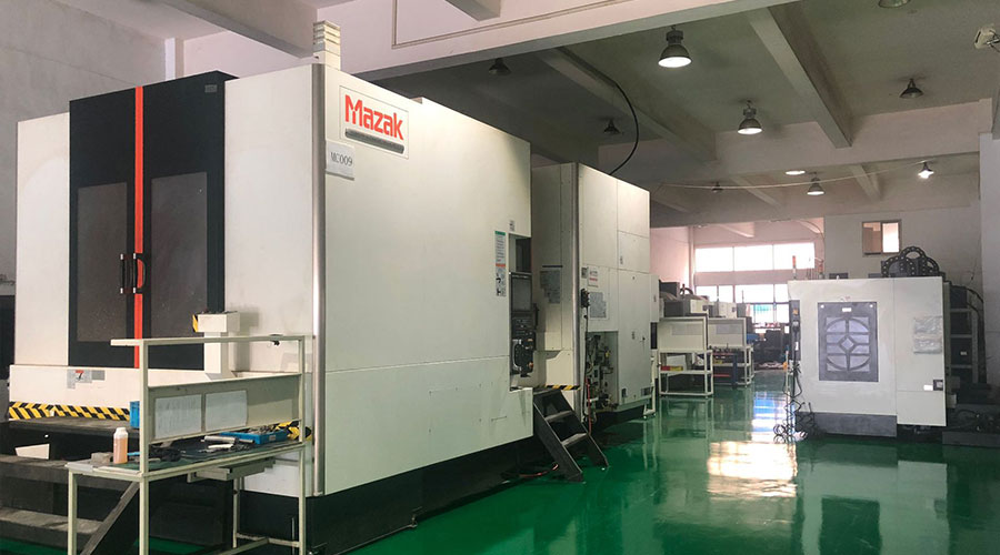 PTJ® provides a full range of Custom Precision cnc machining china services.ISO 9001:2015 &AS-9100 certified. 3, 4 and 5-axis rapid precision CNC machining services including milling, turning to customer specifications,Capable of metal & plastic machined parts with +/-0.005 mm tolerance.Secondary services include CNC and conventional grinding, drilling,die casting,sheet metal and stamping.Providing prototypes, full production runs, technical support and full inspection.Serves the automotive, aerospace, mold&fixture,led lighting,medical,bicycle, and consumer electronics industries. On-time delivery.Tell us a little about your project's budget and expected delivery time. We will strategize with you to provide the most cost-effective services to help you reach your target,Welcome to Contact us ( [email protected] ) directly for your new project.
- 5 Axis Machining
- Cnc Milling
- Cnc Turning
- Machining Industries
- Machining Process
- Surface Treatment
- Metal Machining
- Plastic Machining
- Powder Metallurgy Mold
- Die Casting
- Parts Gallery
- Auto Metal Parts
- Machinery Parts
- LED Heatsink
- Building Parts
- Mobile Parts
- Medical Parts
- Electronic Parts
- Tailored Machining
- Bicycle Parts
- Aluminum Machining
- Titanium Machining
- Stainless Steel Machining
- Copper Machining
- Brass Machining
- Super Alloy Machining
- Peek Machining
- UHMW Machining
- Unilate Machining
- PA6 Machining
- PPS Machining
- Teflon Machining
- Inconel Machining
- Tool Steel Machining
- More Material

