The Five-Axis CNC Machining Of Special-Shaped Bodies
The Five-Axis CNC Machining Of Special-Shaped Bodies
|
Feasible five-axis controlled CNC machining of a special shape part was put forward. Firstly,the 3-dimension model was set up . Secondly,the machining policy and the tool track were planed. Then,VERICUT software was used to realise simulating processing. Finally,the actual machining was finished by using a five-axis controlled CNC machining center with double tables. The process shows the advantages of five-axis controlled CNC machining center. |

With the rapid development of aerospace, weapons, ships, automobiles and other machinery manufacturing industries, the structure of product parts has become increasingly complex and sophisticated. Ordinary 3-axis CNC machining centers can no longer meet the machining needs. The emergence of 5-axis CNC machining centers has adapted to the requirements of product production and has become an unsuccessful one.
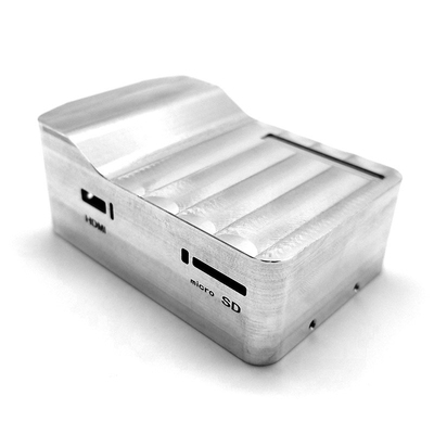
The direction of the development and popularization of machinery manufacturing technology. Aiming at a special-shaped part with an undercut surface (see Figure 1), the five-axis linkage CNC machining center with double turntables can complete the machining of all procedures in one clamping, which solves the problem of curved parts that cannot be completed by three-axis CNC machine tools. Machining.
1 Machining analysis of parts
It can be seen from Figure 1 that the special-shaped body part is mainly composed of a U-shaped inverted cup body, a base and a transition surface, and the machining material is 45 steel. The structure seems simple, but due to the undercut surface, the parts can not be processed by a three-axis CNC machine tool. The five-axis linkage CNC machining center adds two rotary axes on the basis of the three linear axes X, Y, and Z, which can control the axis direction of the tool to change correspondingly with the normal direction of the processed surface, so that it can process complex The curved surface or the curved surface that cannot be completely processed by three-axis. Therefore, the special-shaped parts need to be processed by a five-axis linkage CNC machining center.
2 Parametric modeling of parts
Figure 2 3D model of special-shaped body parts geometric modeling of parts using CAXA Manufacturing Engineer 2011 software [2]

-
(1) Use the stakeout command to generate a U-shaped inverted cup;
-
(2) The base is formed by stretching and adding materials;
- (3) Use the transition command to generate a complete alien body model (see Figure 2).
3 Machining strategy planning rough machining of parts.
In order to improve the machining efficiency, the fixed axis function and layered cutting should be used first, and the flat-bottomed end mill is used to rough the blank to ensure that the large-area machining allowance is removed in the shortest time.
Semi-finished. Utilize the five-axis linkage function and adopt the tool trajectory adapted to the geometric characteristics of the machined surface to perform semi-finish machining on different surfaces to ensure that the large margin after rough machining is removed, so that each machined surface retains an appropriate and uniform finishing margin . finishing. In order to ensure the accuracy, surface quality and efficiency of parts machining, the five-axis linkage function is finally used to finish different surfaces with a ball-end milling cutter.
4 Tool path generation
The generation of tool trajectories is a key link in realizing the CNC machining of curved surfaces. A reasonable tool trajectory can not only improve the quality and efficiency of surface machining, but also give full play to the machining capabilities of CNC machine tools [3-6]
In the finishing process, the U-shaped inverted cup body inverted surface and the upper surface of the base are processed by using a 8 ball end milling cutter and five-axis side milling is used, and the U-shaped inverted cup body cup surface is processed by a 8 ball end milling cutter. Contour of the shaft finely added
In this special-shaped body machining, the roughing adopts 3-axis plane area roughing, and the blank is processed in layers with a 8 flat-bottomed end mill. The plane area roughing can efficiently remove large margins and create conditions for semi-finish machining. . The tool path is shown in Figure 3. In the semi-finishing process, the U-shaped cup body undercut surface and the upper surface of the base use a 8 ball-end milling cutter, which uses 3-axis to generate trajectory and turns to five-axis for five-axis side milling. Five-axis side milling can obtain better results. The surface can improve the cutting efficiency and avoid the zero-speed cutting of the tool during the machining process. The angle between the tool axis and the machining surface can be controlled by setting the machining parameters. The tool axis control parameter settings are shown in Figure 4. The semi-finishing of the inner cup surface of the U-shaped inverted cup uses a 8 ball end milling cutter with 3-axis parametric line finishing. The transition surface is also processed by five-axis side milling. Fine addition of parts
The tool path is shown in Figure 6.
5 Simulation machining of parts
After the tool position file of the part is generated, it is converted into a standard NC program through the multi-axis post-machining setting, and then the generated NC program is imported into the VERICUT7.0 NC simulation machining software for the simulation machining of the part. The machine tool constructed during simulation machining should be consistent with the actual machine tool structure, and the installation position of the parts should also be consistent with the actual machine tool position. Through simulation machining, the rationality of the tool path can be verified, the interference and collision phenomenon in the actual machining process can be checked, and the correctness of the post-machining settings and the generated CNC machining program can be verified, thereby optimizing the tool path and reducing the actual machining of the parts. The error rate has improved the machining efficiency and accuracy of parts.
6 Actual machining of parts on machine tools
After the simulation machining of the part is passed, the optimized CNC machining program can be imported into the actual machine tool for actual machining of the part. The dual-turntable five-axis linkage CNC machining center used in actual machining of parts, the C axis can continuously rotate in the range of 0° to 360 °, and the A axis can swing back and forth in the range of -10° to 100°. The blank is directly clamped with three claws installed on the turntable, and all the parts are processed in one clamping. After testing, the dimensional accuracy and surface quality are all qualified. The processed object is shown in Figure 8.
Link to this article: The Five-Axis CNC Machining Of Special-Shaped Bodies
Reprint Statement: If there are no special instructions, all articles on this site are original. Please indicate the source for reprinting:https://www.cncmachiningptj.com/,thanks!
 PTJ CNC shop produces parts with excellent mechanical properties, accuracy and repeatability from metal and plastic. 5 axis CNC milling available.Machining high-temperature alloy range inclouding inconel machining,monel machining,Geek Ascology machining,Carp 49 machining,Hastelloy machining,Nitronic-60 machining,Hymu 80 machining,Tool Steel machining,etc.,. Ideal for aerospace applications.CNC machining produces parts with excellent mechanical properties, accuracy and repeatability from metal and plastic. 3-axis & 5-axis CNC milling available.We will strategize with you to provide the most cost-effective services to help you reach your target,Welcome to Contact us ( [email protected] ) directly for your new project.

- 5 Axis Machining
- Cnc Milling
- Cnc Turning
- Machining Industries
- Machining Process
- Surface Treatment
- Metal Machining
- Plastic Machining
- Powder Metallurgy Mold
- Die Casting
- Parts Gallery
- Auto Metal Parts
- Machinery Parts
- LED Heatsink
- Building Parts
- Mobile Parts
- Medical Parts
- Electronic Parts
- Tailored Machining
- Bicycle Parts
- Aluminum Machining
- Titanium Machining
- Stainless Steel Machining
- Copper Machining
- Brass Machining
- Super Alloy Machining
- Peek Machining
- UHMW Machining
- Unilate Machining
- PA6 Machining
- PPS Machining
- Teflon Machining
- Inconel Machining
- Tool Steel Machining
- More Material