How to Make a Good Technical Drawing
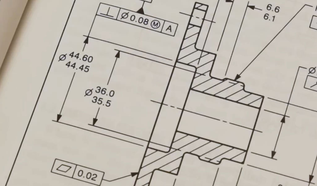
Technical drawing, often referred to as drafting or engineering drawing, serves as the universal language of engineers, architects, manufacturers, and designers. It is a precise method of visually communicating complex ideas, specifications, and instructions for constructing objects, systems, or structures. In an era dominated by digital tools and computer-aided design (CAD), the art of creating a good technical drawing remains foundational to successful project execution, reducing errors, minimizing costs, and ensuring clarity among stakeholders. This article explores the intricacies of how to make a good technical drawing, drawing from historical contexts, modern practices, and industry standards. Whether you are a novice drafter sketching by hand or an experienced professional using advanced software, the principles outlined here emphasize accuracy, readability, and efficiency. By incorporating best practices, tools, techniques, and comparative analyses, this comprehensive guide aims to equip readers with the knowledge to produce drawings that not only meet functional requirements but also stand the test of professional scrutiny. The following sections delve into the subject matter systematically, providing detailed explanations, examples, and tables for enhanced understanding.
Technical drawings have evolved from ancient sketches on papyrus to sophisticated digital models, yet the core objective remains unchanged: to convey information unambiguously. A good technical drawing is not merely an illustration but a blueprint for action, where every line, dimension, and symbol carries weight. Before embarking on the creation process, it is essential to understand that technical drawing demands discipline—precision in measurement, consistency in notation, and foresight in presentation. This article adopts a Wikipedia-style approach, presenting information neutrally and factually, with periodic section headings to organize content scientifically. Subsections are introduced with explanatory text to provide context, ensuring a logical flow. Tables are included for comparisons, such as between traditional and modern tools or various projection methods, to facilitate quick reference and deeper analysis.
Introduction to Technical Drawing
The foundation of any good technical drawing lies in its purpose: to document and communicate design intent clearly and efficiently. Unlike artistic drawings, which prioritize aesthetics and interpretation, technical drawings adhere to strict conventions to eliminate ambiguity. They are used across fields like mechanical engineering, architecture, electrical design, and manufacturing to specify dimensions, materials, tolerances, and assembly instructions. A well-executed drawing can prevent costly mistakes during production, such as misaligned parts or incorrect scaling, and serves as a legal record in patents or contracts.
In practice, creating a good technical drawing begins with defining the scope—what needs to be communicated and to whom. For instance, a machinist requires detailed tolerances, while an architect might focus on spatial relationships. The process involves selecting appropriate views, scales, and symbols, all while ensuring the drawing is legible and scalable. According to engineering best practices, clarity is paramount; overcrowded drawings lead to errors, while sparse ones omit critical details. This introduction sets the stage for exploring historical developments, as understanding the evolution of technical drawing informs modern methods.
History of Technical Drawing
Before delving into specific techniques, it is crucial to appreciate the historical context, which reveals how technical drawing transitioned from rudimentary sketches to standardized practices. The origins of technical drawing trace back to ancient civilizations, where Egyptians used scaled plans for pyramids around 3000 BCE, employing grids for proportion. Similarly, Roman engineers like Vitruvius documented architectural designs in treatises, emphasizing symmetry and measurement.
The Renaissance marked a pivotal advancement with the invention of perspective drawing by Filippo Brunelleschi in the early 15th century, allowing for realistic three-dimensional representations on two-dimensional surfaces. This era saw Leonardo da Vinci's intricate mechanical sketches, blending art and engineering. The Industrial Revolution in the 18th century formalized technical drawing, with Gaspard Monge's development of descriptive geometry in 1799 providing a mathematical basis for orthographic projections. By the 19th century, standardized blueprints emerged, using Prussian blue dye for reproductions.
The 20th century introduced computer-aided drafting, with Ivan Sutherland's Sketchpad in 1963 pioneering interactive CAD systems. Today, software like AutoCAD and SolidWorks dominates, enabling rapid iterations and 3D modeling. This historical progression underscores the importance of precision, a theme echoed in contemporary standards like ISO 128, which codifies symbols and layouts. Understanding this evolution helps modern drafters appreciate why certain conventions, such as line types, persist.
Evolution of Standards in Technical Drawing
Historical advancements laid the groundwork for standards that ensure interoperability. Prior to standardization, drawings varied by region, leading to confusion in international trade. The establishment of the International Organization for Standardization (ISO) in 1947 unified practices, with ISO 128 defining general principles for technical drawings. In the United States, the American National Standards Institute (ANSI) developed ASME Y14.5 for geometric dimensioning and tolerancing (GD&T), first published in 1949 and updated regularly.
These standards evolved to accommodate digital tools; for example, ISO 16792 addresses digital product definition data practices. A key milestone was the shift from manual to CAD standards in the 1980s, reducing errors by up to 50% in manufacturing. Today, standards emphasize sustainability, incorporating notations for eco-friendly materials. This subsection highlights how history influences current best practices, leading into tools.
Tools and Materials for Technical Drawing
Selecting the right tools is the first step in creating a good technical drawing, as they directly impact accuracy and efficiency. Traditional manual tools provide tactile feedback, ideal for beginners, while digital tools offer precision and speed for professionals. Materials like paper or digital files must be chosen based on the drawing's purpose—archival paper for long-term storage or vector formats for scalability.
Common tools include pencils for sketching, erasers for corrections, and rulers for straight lines. For manual drafting, a drawing board and T-square ensure parallelism. Digital alternatives, such as tablets with styluses, bridge the gap. The choice between manual and digital often depends on the project's complexity; simple sketches may suffice with paper, but intricate designs require CAD software.
Traditional Manual Tools
Manual tools form the bedrock of technical drawing, offering affordability and portability. A drafting table, angled for comfort, paired with a T-square, allows for horizontal lines, while set squares create angles like 30°, 45°, or 60°. Compasses draw circles and arcs, essential for geometric constructions, and French curves handle irregular shapes.
Pencils range from hard (H grades) for light lines to soft (B grades) for bold outlines. Ink pens, like technical pens with nib sizes from 0.1mm to 2.0mm, provide permanent lines. Erasers, shielding templates, and dusting brushes maintain cleanliness. These tools, though labor-intensive, teach fundamental skills like hand-eye coordination.
Comparison of Manual Tools
To aid selection, consider this table comparing common manual tools:
| Tool | Purpose | Advantages | Disadvantages | Examples |
|---|---|---|---|---|
| T-Square | Drawing horizontal lines | Ensures parallelism; inexpensive | Limited to straight lines; requires flat surface | Alvin T-Square, 24-inch |
| Set Square | Creating angled lines | Versatile angles; durable plastic or metal | Fixed angles only | Staedtler 45/90 Triangle |
| Compass | Arcs and circles | Precise radii; adjustable | Prone to slippage on paper | Rotring Compass Set |
| French Curve | Irregular curves | Flexible shapes; reusable | Requires practice for smooth lines | Alvin French Curve Set |
| Technical Pen | Inking final lines | Uniform thickness; waterproof ink | Clogs easily; expensive refills | Rotring Isograph, 0.35mm |
This table illustrates trade-offs, such as precision versus ease of use. Manual tools are ideal for educational settings but less efficient for revisions compared to digital counterparts.
Digital Tools and Software
Digital tools revolutionize technical drawing by enabling quick edits and 3D visualizations. CAD software like AutoCAD allows for 2D drafting with layers for organization, while 3D programs like SolidWorks simulate assemblies. Hardware includes graphics tablets (e.g., Wacom Intuos) for natural input and high-resolution monitors for detail.
Cloud-based tools, such as Onshape, facilitate collaboration, with real-time sharing. Best practices include using templates for consistency and exporting to PDF for universal viewing. Digital tools reduce material waste and support parametric design, where changing one dimension updates the entire model.
Comparison of CAD Software
For decision-making, here's a detailed table comparing popular CAD software:
| Software | Type (2D/3D) | Key Features | Cost | Best For | Limitations |
|---|---|---|---|---|---|
| AutoCAD | Both | Layer management, annotation tools, API customization | Subscription (~$1,775/year) | General engineering, architecture | Steep learning curve; resource-intensive |
| SolidWorks | 3D | Parametric modeling, simulation, assembly checks | ~$3,995 (one-time) + maintenance | Mechanical design, product development | Windows-only; high cost for small users |
| Fusion 360 | Both | Cloud collaboration, CAM integration, generative design | Free for hobbyists; $545/year pro | Prototyping, small teams | Internet-dependent; limited advanced features in free version |
| FreeCAD | Both | Open-source, modular, Python scripting | Free | Beginners, open-source projects | Less polished UI; fewer commercial plugins |
| SketchUp | 3D | Intuitive interface, 3D warehouse for models | Free basic; $299/year pro | Architecture, interior design | Not ideal for precise engineering tolerances |
This comparison highlights factors like cost and usability, aiding in tool selection based on project needs. Digital tools excel in complex projects but require training to maximize benefits.
Basic Principles of Technical Drawing
Principles guide the creation of effective drawings, ensuring they are accurate, complete, and easy to interpret. Key principles include orthographic projection for multi-view representation, dimensioning for size specification, and tolerancing for allowable variations. Scale is critical; drawings must be proportional, often at 1:1 for details or reduced for large objects.
Line types convey meaning: continuous for visible edges, dashed for hidden features, and centerlines for symmetry. Symbols standardize communication, such as arrows for dimensions or hatches for sections. Adhering to these principles prevents misinterpretation, as seen in manufacturing where incorrect lines can lead to faulty parts.
Projection Methods
Projection methods depict 3D objects in 2D, with orthographic being the most common for technical accuracy. In orthographic projection, views are projected perpendicularly, showing front, top, and side without distortion. First-angle (European) and third-angle (American) conventions differ in view placement.
Isometric projection offers a 3D-like view at 30° angles, useful for visualization but not for precise measurements. Perspective projection adds realism but is less common in technical drawings due to distortion.
Table of Projection Methods Comparison
| Method | Description | Advantages | Disadvantages | Applications |
|---|---|---|---|---|
| Orthographic | Multiple 2D views from perpendicular angles | Accurate dimensions; no distortion | Requires multiple views for 3D understanding | Engineering blueprints, manufacturing |
| Isometric | 3D representation with equal angles | Easy to visualize; single view suffices | Foreshortened measurements; less precise | Assembly instructions, illustrations |
| Oblique | 3D with one face parallel to plane | Simple to draw; shows depth | Distorted proportions | Quick sketches, cabinetry |
| Perspective | Converging lines for realism | Aesthetic appeal; natural view | Difficult to measure; distortion at edges | Architectural renderings, presentations |
This table compares methods, showing orthographic's superiority for precision. Choose based on the drawing's purpose—technical accuracy or visual appeal.
Line Types and Conventions
Lines are the building blocks of technical drawings, each type serving a specific function to enhance clarity. Visible lines are thick and continuous, representing edges in direct view. Hidden lines, dashed and thinner, indicate obscured features. Centerlines, alternating long and short dashes, denote axes of symmetry or hole centers.
Dimension lines are thin with arrows, extension lines connect features to dimensions, and section lines (hatches) fill cut areas. Consistency in line weight—0.7mm for outlines, 0.3mm for dimensions—improves readability. Conventions like these, standardized by ISO, ensure universal understanding.
Techniques for Creating Good Technical Drawings
Techniques transform principles into practice, focusing on step-by-step processes for high-quality output. Start with rough sketches to conceptualize, then refine with precise measurements. Use grids or guidelines for alignment, and layer information logically—geometry first, dimensions last. For good drawings, prioritize neatness; smudges or inconsistent lines undermine professionalism.
In digital techniques, utilize snaps and constraints for accuracy. Manual techniques emphasize steady hands and proper tool handling. Advanced techniques include GD&T for complex tolerances and exploded views for assemblies.
Step-by-Step Drawing Process
The process begins with preparation: gather references, select scale, and choose views. Sketch lightly, then darken outlines. Add dimensions, tolerances, and notes, ensuring no overlaps. Review for errors, perhaps using checklists for completeness.
For example, in machining drawings, include isometric views for context and section views for internals. Iterate based on feedback, as revisions are common in design cycles.
Best Practices for Dimensioning
Dimensioning requires placing numbers clearly, avoiding redundancy. Use unidirectional alignment for readability, and chain dimensions for sequences. Tolerances specify variations, like ±0.01mm for precision parts. Avoid dimensioning hidden lines unless necessary.
Avoiding Common Mistakes
Common pitfalls include over-dimensioning, leading to conflicts, or poor scale choice, distorting proportions. Use checklists: verify views align, lines are consistent, and symbols are standard. Digital errors like layer mismanagement can be mitigated with templates.
Standards and Conventions in Technical Drawing
Standards provide a framework for consistency, with ISO and ASME leading globally. Conventions cover title blocks, which include part name, material, scale, and revisions. GD&T symbols control form, orientation, and location, reducing ambiguity.
Industry-specific conventions exist; mechanical drawings emphasize tolerances, while architectural focus on sections. Compliance ensures drawings are manufacturable and legally sound.
International Standards Comparison
Standards vary by region but converge on core elements. Here's a table:
| Standard | Organization | Focus Areas | Regions | Key Features |
|---|---|---|---|---|
| ISO 128 | ISO | General principles, line types | Global | Universal symbols, projection methods |
| ASME Y14.5 | ASME | GD&T | USA | Detailed tolerancing, datum systems |
| BS 8888 | BSI | Technical product documentation | UK | Integration with ISO, manufacturing notes |
| DIN 6 | DIN | Views and sections | Germany | Precise dimensioning rules |
| JIS B 0001 | JIS | Mechanical engineering drawings | Japan | Emphasis on assembly drawings |
This comparison aids in selecting standards for international projects.
Advanced Topics in Technical Drawing
Advanced topics extend basic skills, including 3D modeling for simulations and BIM for building information modeling. Parametric design allows dynamic adjustments, and VR integration enables immersive reviews.
For sustainability, drawings now include lifecycle notes. AI-assisted drafting predicts errors, enhancing efficiency.
Geometric Dimensioning and Tolerancing (GD&T)
GD&T uses symbols to define allowable variations, like flatness or parallelism. It supersedes traditional tolerancing for complex parts, ensuring fit and function. Datums establish reference frames, critical for assembly.
GD&T Symbols Table
| Symbol | Meaning | Application | Example |
|---|---|---|---|
| ⌖ | Position | Locates features | Hole placement |
| ⏥ | Flatness | Surface evenness | Tabletop |
| ∥ | Parallelism | Alignment | Shaft to base |
| ⊥ | Perpendicularity | Right angles | Wall to floor |
| ○ | Circularity | Roundness | Cylinder |
This table summarizes common symbols for quick reference.
Applications and Case Studies
Technical drawings apply to diverse fields. In automotive, they specify engine components; in aerospace, aerodynamic profiles. Case studies, like the Boeing 787's CAD-driven design, show how good drawings reduce development time by 30%.
Case Study: Bridge Construction
In the Millennium Bridge project, detailed sections prevented vibration issues post-construction through iterative drawings.
Conclusion
Mastering technical drawing requires blending art, science, and practice. By following the guidelines herein—from tools to standards—you can create drawings that are not only good but exemplary, fostering innovation and precision in your field. Continuous learning, through courses or software updates, keeps skills sharp.
Reprint Statement: If there are no special instructions, all articles on this site are original. Please indicate the source for reprinting:https://www.cncmachiningptj.com/,thanks!
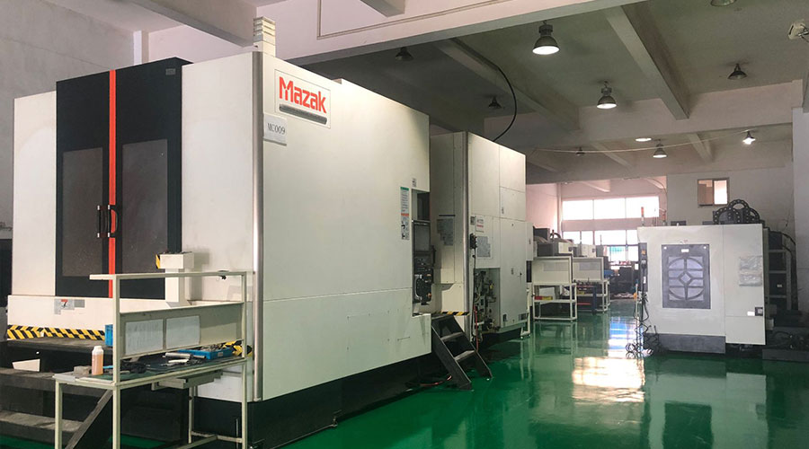 PTJ® provides a full range of Custom Precision cnc machining china services.ISO 9001:2015 &AS-9100 certified. 3, 4 and 5-axis rapid precision CNC machining services including milling, turning to customer specifications,Capable of metal & plastic machined parts with +/-0.005 mm tolerance.Secondary services include CNC and conventional grinding, drilling,die casting,sheet metal and stamping.Providing prototypes, full production runs, technical support and full inspection.Serves the automotive, aerospace, mold&fixture,led lighting,medical,bicycle, and consumer electronics industries. On-time delivery.Tell us a little about your project's budget and expected delivery time. We will strategize with you to provide the most cost-effective services to help you reach your target,Welcome to Contact us ( [email protected] ) directly for your new project.

- 5 Axis Machining
- Cnc Milling
- Cnc Turning
- Machining Industries
- Machining Process
- Surface Treatment
- Metal Machining
- Plastic Machining
- Powder Metallurgy Mold
- Die Casting
- Parts Gallery
- Auto Metal Parts
- Machinery Parts
- LED Heatsink
- Building Parts
- Mobile Parts
- Medical Parts
- Electronic Parts
- Tailored Machining
- Bicycle Parts
- Aluminum Machining
- Titanium Machining
- Stainless Steel Machining
- Copper Machining
- Brass Machining
- Super Alloy Machining
- Peek Machining
- UHMW Machining
- Unilate Machining
- PA6 Machining
- PPS Machining
- Teflon Machining
- Inconel Machining
- Tool Steel Machining
- More Material

