Microstructure Damage in Polymer-Based Composites during Machining

Polymer-based composites, also known as polymer matrix composites (PMCs), are advanced materials composed of a polymeric matrix reinforced with fibers, particles, or other fillers to enhance mechanical, thermal, and electrical properties. These materials are widely utilized across industries such as aerospace, automotive, marine, and biomedical due to their high strength-to-weight ratio, corrosion resistance, and design flexibility. However, the machining of PMCs, necessary for achieving dimensional accuracy and functional features, presents significant challenges due to their heterogeneous and anisotropic microstructure. Machining processes such as drilling, milling, turning, and abrasive cutting often induce microstructural damage, compromising the material’s integrity, performance, and service life. This article explores the mechanisms, types, and effects of microstructure damage in polymer-based composites during machining, providing a comprehensive analysis of influencing factors, detection methods, mitigation strategies, and recent research advancements. Detailed tables are included to facilitate comparison of machining parameters, damage types, and material responses.
The microstructure of PMCs typically consists of a ductile polymer matrix (e.g., epoxy, polyester, or thermoplastic resins) reinforced with brittle, high-strength fibers (e.g., carbon, glass, or aramid) or particulate fillers. The distinct properties of these constituents lead to complex material removal mechanisms during machining, resulting in damage such as delamination, fiber pull-out, matrix cracking, and surface irregularities. Understanding these damage mechanisms is critical for optimizing machining processes, improving component reliability, and advancing composite manufacturing technologies. This article adopts a scientific tone, drawing on peer-reviewed literature and experimental data to present a rigorous examination of the subject, with a focus on recent findings up to June 2025.
Fundamentals of Polymer-Based Composites
Composition and Structure
Polymer-based composites are heterogeneous materials comprising a continuous polymer matrix and discontinuous reinforcing phases. The matrix serves as a binder, transferring loads to the reinforcement while protecting it from environmental degradation. Common matrix materials include thermosetting resins (e.g., epoxy, polyester, vinyl ester) and thermoplastics (e.g., polyetheretherketone (PEEK), polypropylene). Reinforcements are typically fibers (e.g., carbon fiber, glass fiber, aramid fiber), particles (e.g., silica, carbon nanotubes), or hybrid combinations, arranged in various configurations such as unidirectional laminates, woven fabrics, or randomly oriented mats. The volume fraction, orientation, and interfacial bonding between matrix and reinforcement significantly influence the composite’s mechanical properties and machinability.
The microstructure of PMCs is inherently anisotropic, with properties varying along different directions due to fiber orientation. For example, carbon-fiber-reinforced polymers (CFRPs) exhibit high tensile strength along the fiber direction but lower strength transverse to it. This anisotropy complicates machining, as cutting forces interact differently with fibers and matrix, leading to distinct damage patterns. The interfacial region between matrix and reinforcement is particularly critical, as weak bonding can exacerbate damage during machining, such as fiber debonding or pull-out.
Mechanical Properties
The mechanical properties of PMCs, including tensile strength, compressive strength, shear strength, and fracture toughness, are governed by the properties of the constituents and their interactions. For instance, CFRPs can achieve tensile strengths exceeding 2 GPa along the fiber direction, while glass-fiber-reinforced polymers (GFRPs) offer moderate strength (0.5–1 GPa) but superior corrosion resistance. The matrix contributes ductility and toughness, mitigating brittle failure of the reinforcement. However, the mismatch in stiffness and thermal expansion between matrix and reinforcement can induce residual stresses during manufacturing, which may be exacerbated during machining, leading to microcracks or delamination.
Applications
PMCs are integral to high-performance applications requiring lightweight, durable materials. In aerospace, CFRPs are used in airframes, wings, and turbine blades, reducing fuel consumption while maintaining structural integrity. In automotive industries, GFRPs and natural-fiber-reinforced polymers (NFRPs) are employed in body panels and interiors to enhance fuel efficiency. Biomedical applications leverage PMCs for prosthetics and implants due to their biocompatibility and customizable properties. These diverse applications necessitate precise machining to achieve functional geometries, making the study of microstructure damage a critical research area.
Machining Processes for Polymer-Based Composites
Overview of Machining Techniques
Machining of PMCs involves material removal to achieve desired shapes, dimensions, or surface finishes. Common machining processes include:
-
Drilling: Used to create holes for fasteners, prevalent in aerospace assemblies. Drilling induces significant damage due to thrust forces and torque, particularly delamination at hole entry and exit.
-
Milling: Employed for shaping surfaces or slots, involving peripheral or end milling. Milling can cause surface roughness and fiber protrusion, especially in high-speed operations.
-
Turning: Applied to cylindrical components, less common for PMCs due to their planar nature. Turning may lead to fiber fracture and matrix smearing.
-
Abrasive Cutting: Utilizes abrasive tools (e.g., diamond or cubic boron nitride) for precision cutting, often resulting in thermal damage due to friction.
Non-conventional machining techniques, such as laser cutting, abrasive waterjet machining, and electrical discharge machining, are also used but are outside the scope of this article, which focuses on conventional mechanical machining.
Material Removal Mechanisms
The material removal mechanisms in PMCs differ fundamentally from those in metals due to the composite’s heterogeneous structure. During machining, the cutting tool interacts with both the soft matrix and hard reinforcement, leading to distinct failure modes:
-
Matrix Failure: The polymer matrix undergoes plastic deformation, cracking, or smearing, depending on its ductility and the cutting conditions. Thermosetting matrices are prone to brittle fracture, while thermoplastics may exhibit ductile flow.
-
Fiber Failure: Fibers experience bending, buckling, or fracture, influenced by their orientation relative to the cutting direction. Fibers oriented perpendicular to the tool path are more susceptible to pull-out, while parallel fibers may fracture cleanly.
-
Interface Failure: The fiber-matrix interface may debond under shear or tensile stresses, leading to delamination or fiber detachment.
These mechanisms are influenced by machining parameters (e.g., cutting speed, feed rate, tool geometry), tool material, and workpiece properties, as discussed in subsequent sections.
Types of Microstructure Damage in Machining
Delamination
Delamination is the separation of adjacent plies in laminated composites, caused by out-of-plane stresses during machining. It is the most prevalent form of damage, particularly in drilling, where thrust forces push layers apart at the hole exit (push-out delamination) or peel them at the entry (peel-up delamination). Delamination reduces the composite’s load-bearing capacity and fatigue life, compromising structural integrity. Factors contributing to delamination include high thrust forces, low interlaminar shear strength, and improper tool geometry. For example, twist drills with high point angles exacerbate delamination compared to step drills or core drills.
Fiber Pull-Out
Fiber pull-out occurs when fibers are extracted from the matrix due to weak interfacial bonding or excessive shear forces. This damage is common in milling and drilling, particularly when fibers are oriented at 90° to the cutting direction. Fiber pull-out creates surface voids, reducing surface quality and promoting stress concentrations that may initiate cracks under service loads. The extent of pull-out depends on fiber type (e.g., carbon fibers are more resistant than glass fibers), matrix toughness, and cutting parameters.
Matrix Cracking
Matrix cracking involves the formation of micro- or macro-cracks in the polymer matrix, often initiated by tensile or shear stresses during machining. Cracks may propagate along the fiber-matrix interface or through the matrix, leading to reduced stiffness and strength. Thermosetting matrices, such as epoxy, are more susceptible to cracking than ductile thermoplastics like PEEK. Matrix cracking is prevalent in high-feed-rate operations, where rapid material removal induces localized stress concentrations.
Surface Roughness and Burr Formation
Surface roughness refers to irregularities on the machined surface, resulting from fiber protrusion, matrix smearing, or tool wear. High surface roughness compromises aesthetic and functional properties, such as aerodynamic performance in aerospace components. Burr formation, the protrusion of uncut fibers or matrix material at the machined edge, is common in milling and drilling. Burrs require secondary finishing operations, increasing manufacturing costs. Surface quality is influenced by tool material (e.g., polycrystalline diamond (PCD) tools yield smoother surfaces than carbide tools) and cutting speed.
Thermal Damage
Thermal damage arises from frictional heat generated during machining, particularly in high-speed operations or with abrasive tools. Elevated temperatures can soften or degrade the polymer matrix, leading to smearing, burning, or decomposition. For example, epoxy matrices degrade above 200°C, while PEEK remains stable up to 300°C. Thermal damage is more pronounced in CFRPs due to the low thermal conductivity of carbon fibers, which traps heat at the cutting zone. Cooling strategies, such as cryogenic machining, mitigate thermal effects but may introduce additional complexities.
Table 1: Comparison of Microstructure Damage Types in PMC Machining
|
Damage Type |
Description |
Primary Causes |
Affected Properties |
Common Machining Processes |
Mitigation Strategies |
|---|---|---|---|---|---|
|
Delamination |
Separation of plies due to out-of-plane stresses |
High thrust forces, low interlaminar shear strength, improper tool geometry |
Load-bearing capacity, fatigue life |
Drilling, milling |
Use of backing plates, low feed rates, step drills |
|
Fiber Pull-Out |
Extraction of fibers from matrix due to shear forces |
Weak interfacial bonding, high feed rates, perpendicular fiber orientation |
Surface quality, stress concentration |
Milling, drilling |
High cutting speeds, PCD tools, optimized feed |
|
Matrix Cracking |
Cracks in polymer matrix from tensile/shear stresses |
High feed rates, brittle matrix, tool wear |
Stiffness, strength |
Drilling, milling, turning |
Low feed rates, ductile matrices, sharp tools |
|
Surface Roughness |
Surface irregularities from fiber protrusion or matrix smearing |
Tool wear, high feed rates, improper tool material |
Aerodynamic performance, aesthetics |
Milling, drilling |
PCD tools, high cutting speeds, finishing passes |
|
Thermal Damage |
Matrix degradation due to frictional heat |
High cutting speeds, low thermal conductivity, inadequate cooling |
Matrix integrity, mechanical properties |
Milling, abrasive cutting |
Cryogenic cooling, low cutting speeds |
Notes: This table summarizes the primary types of microstructure damage observed in PMC machining, based on literature up to 2025. Data is derived from experimental studies and reviews, including those by Sheikh-Ahmad (2009) and recent publications in Composites Science and Technology.
Factors Influencing Microstructure Damage
Machining Parameters
Machining parameters, including cutting speed, feed rate, and depth of cut, significantly affect damage severity. High cutting speeds (e.g., >200 m/min) reduce delamination by minimizing tool-workpiece contact time but may increase thermal damage due to friction. Low feed rates (e.g., <0.1 mm/rev) decrease thrust forces, reducing delamination and fiber pull-out, but prolong machining time, increasing costs. Optimal parameter selection depends on the composite type, tool material, and machining process. For instance, drilling CFRPs at 50 m/min and 0.05 mm/rev minimizes delamination compared to higher speeds or feeds.
Tool Geometry and Material
Tool geometry, including rake angle, clearance angle, and point angle, influences cutting forces and damage. For drilling, low point angles (e.g., 90°) reduce thrust forces, minimizing delamination, while high rake angles improve chip evacuation, reducing matrix smearing. Tool materials such as PCD and cubic boron nitride (CBN) offer superior wear resistance and thermal conductivity compared to carbide tools, yielding better surface quality and reduced damage. However, PCD tools are costly, limiting their use in low-volume production.
Workpiece Properties
The properties of the PMC, including fiber type, matrix material, and layup configuration, dictate damage susceptibility. CFRPs are more prone to thermal damage due to low thermal conductivity, while GFRPs exhibit higher delamination due to lower interlaminar strength. Thermoplastic matrices, such as PEEK, resist cracking better than brittle epoxy matrices. Layup orientation affects damage patterns; for example, 0°/90° laminates experience less delamination than ±45° configurations due to higher shear resistance.
Environmental Conditions
Environmental factors, such as temperature and humidity, influence machining outcomes. Elevated temperatures soften the matrix, increasing smearing, while high humidity may weaken fiber-matrix interfaces, promoting delamination. Cryogenic machining, using liquid nitrogen, reduces thermal damage but requires specialized equipment, limiting its industrial adoption.
Detection and Characterization of Microstructure Damage
Non-Destructive Testing (NDT) Methods
Non-destructive testing is essential for assessing microstructure damage without compromising component integrity. Common NDT methods include:
-
Ultrasonic Testing: Detects delamination and voids by analyzing sound wave propagation. Effective for internal defects but less sensitive to surface damage.
-
X-Ray Computed Tomography (CT): Provides 3D visualization of internal microstructure, identifying cracks, delamination, and fiber damage. High resolution but costly and time-consuming.
-
Digital Image Correlation (DIC): Measures surface strain and deformation, useful for real-time monitoring during machining. Limited to surface analysis.
-
Thermography: Detects thermal damage by mapping temperature variations. Suitable for high-speed machining but less effective for subsurface defects.
Recent advancements, such as machine learning-enhanced X-ray CT, enable automated damage detection with improved accuracy.
Quantitative Metrics
Damage severity is quantified using metrics such as:
-
Delamination Factor (F_d): Ratio of the maximum delaminated diameter to the nominal hole diameter in drilling. F_d > 1.1 indicates significant damage.
-
Surface Roughness (R_a): Average deviation of the machined surface profile, typically measured in micrometers. R_a > 5 μm suggests poor surface quality.
-
Damage Volume: Volume of material affected by cracks or voids, measured via X-ray CT. Higher volumes correlate with reduced mechanical performance.
These metrics facilitate comparison across studies and guide process optimization.
Table 2: NDT Methods for Microstructure Damage Detection
|
NDT Method |
Principle |
Detected Damage Types |
Advantages |
Limitations |
Applications |
|---|---|---|---|---|---|
|
Ultrasonic Testing |
Sound wave propagation |
Delamination, voids |
Cost-effective, rapid |
Limited surface sensitivity |
Aerospace, automotive |
|
X-Ray CT |
3D imaging via X-ray absorption |
Cracks, delamination, fiber damage |
High resolution, comprehensive |
Expensive, time-consuming |
Research, high-value components |
|
Digital Image Correlation |
Surface strain measurement |
Surface deformation, cracks |
Real-time monitoring |
Surface-only analysis |
Experimental studies |
|
Thermography |
Temperature mapping |
Thermal damage, matrix degradation |
Non-contact, fast |
Subsurface detection limited |
High-speed machining |
Notes: This table compares NDT methods based on their principles, capabilities, and applications, drawing on studies from Polymer Composites and Composites Science and Technology.
Mitigation Strategies for Microstructure Damage
Process Optimization
Optimizing machining parameters is a primary strategy for minimizing damage. Low feed rates and moderate cutting speeds reduce mechanical and thermal stresses, while adaptive control systems adjust parameters in real-time based on force or temperature feedback. For example, drilling CFRPs at 0.05 mm/rev and 50 m/min with a PCD tool minimizes delamination compared to higher feeds or speeds.
Advanced Tooling
Advanced tool materials, such as PCD and CBN, reduce wear and heat generation, improving surface quality and reducing damage. Novel tool geometries, such as double-point-angle drills or serrated edges, distribute cutting forces more evenly, mitigating delamination. Coatings, such as diamond-like carbon (DLC), enhance tool durability and reduce friction, further minimizing thermal damage.
Support Structures
Using backing plates or sacrificial layers during drilling prevents push-out delamination by supporting the exit side of the workpiece. For milling, clamping fixtures stabilize thin-walled components, reducing deformation and burr formation. These strategies are particularly effective for laminated composites with low interlaminar strength.
Cooling Techniques
Cooling methods, such as minimum quantity lubrication (MQL) and cryogenic cooling, mitigate thermal damage. MQL delivers a fine mist of lubricant, reducing friction and heat, while cryogenic cooling uses liquid nitrogen to maintain low temperatures, preserving matrix integrity. However, cryogenic systems are complex and costly, limiting their widespread adoption.
Recent Research Advancements
Machine Learning and Damage Prediction
Machine learning techniques, such as convolutional neural networks and autoencoders, are increasingly applied to predict and detect microstructure damage. These algorithms analyze NDT data (e.g., X-ray CT images) to identify damage patterns with high accuracy. For instance, a 2024 study in Composites Science and Technology demonstrated a 95% accuracy in detecting delamination using a deep learning model trained on ultrasonic data.
Multi-Scale Modeling
Multi-scale modeling integrates mesoscopic and macroscopic approaches to simulate damage evolution during machining. Finite element models (FEM) coupled with extended FEM (XFEM) predict crack propagation and delamination, validated against experimental data. These models guide tool design and parameter optimization, reducing trial-and-error in process development.
Sustainable Machining
Recent research emphasizes sustainable machining practices, such as using biodegradable lubricants and energy-efficient processes. A 2025 study in Polymer Composites explored the use of vegetable-based MQL in CFRP drilling, achieving comparable damage reduction to conventional lubricants while minimizing environmental impact.
Future Directions
Future research should focus on:
-
Hybrid Machining: Combining conventional and non-conventional techniques (e.g., laser-assisted drilling) to reduce damage while improving efficiency.
-
Smart Manufacturing: Integrating sensors and IoT for real-time damage monitoring and adaptive control.
-
Recyclable Composites: Developing PMCs with enhanced machinability and recyclability to support circular economies.
Conclusion
Microstructure damage in polymer-based composites during machining is a complex phenomenon influenced by material properties, machining parameters, tool design, and environmental conditions. Delamination, fiber pull-out, matrix cracking, surface roughness, and thermal damage are prevalent, impacting component performance and reliability. Advances in NDT, process optimization, advanced tooling, and computational modeling offer promising solutions, while emerging trends in machine learning and sustainable machining pave the way for future innovations. This article provides a comprehensive overview, supported by detailed tables, to guide researchers, engineers, and manufacturers in addressing this critical challenge.
Reprint Statement: If there are no special instructions, all articles on this site are original. Please indicate the source for reprinting:https://www.cncmachiningptj.com/,thanks!
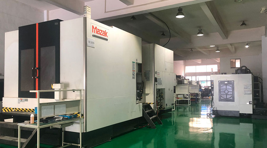 PTJ® provides a full range of Custom Precision cnc machining china services.ISO 9001:2015 &AS-9100 certified. 3, 4 and 5-axis rapid precision CNC machining services including milling, turning to customer specifications,Capable of metal & plastic machined parts with +/-0.005 mm tolerance.Secondary services include CNC and conventional grinding, drilling,die casting,sheet metal and stamping.Providing prototypes, full production runs, technical support and full inspection.Serves the automotive, aerospace, mold&fixture,led lighting,medical,bicycle, and consumer electronics industries. On-time delivery.Tell us a little about your project's budget and expected delivery time. We will strategize with you to provide the most cost-effective services to help you reach your target,Welcome to Contact us ( [email protected] ) directly for your new project.

- 5 Axis Machining
- Cnc Milling
- Cnc Turning
- Machining Industries
- Machining Process
- Surface Treatment
- Metal Machining
- Plastic Machining
- Powder Metallurgy Mold
- Die Casting
- Parts Gallery
- Auto Metal Parts
- Machinery Parts
- LED Heatsink
- Building Parts
- Mobile Parts
- Medical Parts
- Electronic Parts
- Tailored Machining
- Bicycle Parts
- Aluminum Machining
- Titanium Machining
- Stainless Steel Machining
- Copper Machining
- Brass Machining
- Super Alloy Machining
- Peek Machining
- UHMW Machining
- Unilate Machining
- PA6 Machining
- PPS Machining
- Teflon Machining
- Inconel Machining
- Tool Steel Machining
- More Material

