Low-Damage Machining Path and Surface Energy Optimization in CNC Machining of PTFE Materials for Aerospace Insulation Systems
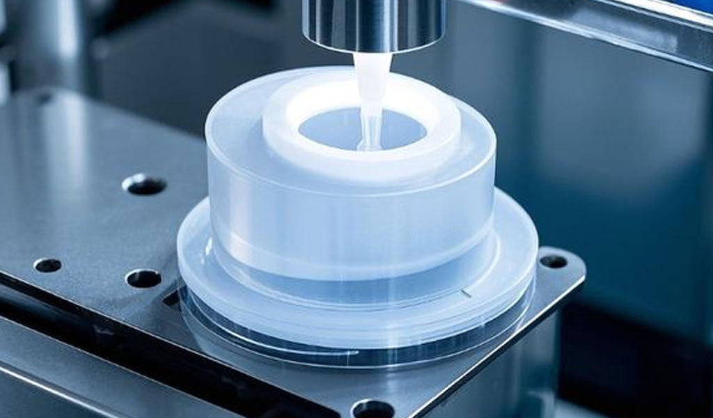
Polytetrafluoroethylene (PTFE), commonly known by its brand name Teflon, is a fluoropolymer renowned for its exceptional chemical inertness, low friction coefficient, high thermal stability, and electrical insulation properties. These characteristics make PTFE an ideal material for aerospace insulation systems, where components must withstand extreme temperatures, corrosive environments, and high electrical demands while maintaining structural integrity and precision. CNC (Computer Numerical Control) machining is the preferred method for fabricating PTFE parts due to its precision, repeatability, and ability to produce complex geometries. However, machining PTFE presents unique challenges due to its softness, high thermal expansion coefficient, and susceptibility to deformation under mechanical stress. These properties necessitate specialized techniques to minimize surface and subsurface damage while optimizing energy efficiency during machining.
This article explores the principles and practices of low-damage machining paths and surface energy optimization in CNC machining of PTFE for aerospace insulation systems. It delves into the material properties of PTFE, the mechanics of CNC machining, strategies for minimizing damage, and methods for optimizing energy consumption. Detailed tables are provided to compare machining parameters, tool selections, and surface finish outcomes, offering a comprehensive resource for researchers, engineers, and manufacturers. The discussion is grounded in recent advancements and scientific studies, ensuring a rigorous and evidence-based approach to the subject.
Material Properties of PTFE
PTFE is a synthetic fluoropolymer composed of carbon and fluorine atoms, characterized by a high molecular weight and a crystalline structure. Its key properties relevant to CNC machining and aerospace applications include:
-
Chemical Inertness: PTFE resists most acids, bases, and solvents, making it suitable for environments with corrosive chemicals, such as those encountered in aerospace fuel systems.
-
Low Friction Coefficient: With a coefficient of friction as low as 0.05–0.10, PTFE is ideal for components requiring minimal wear, such as bearings and seals.
-
Thermal Stability: PTFE remains stable at temperatures up to 260°C (500°F), with a melting point of approximately 327°C (621°F), allowing it to perform in high-temperature aerospace environments.
-
Electrical Insulation: PTFE’s high dielectric strength (60–100 kV/mm) and low dielectric constant (2.1) make it an excellent insulator for wiring and electronic components.
-
Mechanical Properties: PTFE is soft (Shore D hardness of 50–65) and has low tensile strength (20–30 MPa), which poses challenges during machining due to its susceptibility to deformation and creep.
-
Thermal Conductivity: PTFE has low thermal conductivity (0.25 W/m·K), leading to heat buildup during machining, which can cause thermal expansion and dimensional inaccuracies.
These properties make PTFE a preferred material for aerospace insulation systems, including cable insulation, gaskets, and seals, but they also complicate the machining process. The softness of PTFE can lead to tool chatter, burr formation, and surface imperfections, while its low thermal conductivity necessitates careful heat management to prevent deformation.
CNC Machining of PTFE: Challenges and Considerations
CNC machining is a subtractive manufacturing process that uses computer-controlled tools to remove material from a workpiece, shaping it into the desired form. For PTFE, CNC machining is favored over other methods like injection molding due to PTFE’s high melt viscosity, which prevents it from being processed by traditional molding techniques. However, machining PTFE requires careful consideration of its unique properties to achieve high-quality parts with minimal damage.
Challenges in Machining PTFE
-
Softness and Deformation: PTFE’s low rigidity leads to deformation under cutting forces, resulting in tool chatter, poor surface finish, and dimensional inaccuracies. Excessive pressure can cause the material to smear or deform, compromising part integrity.
-
Thermal Expansion: PTFE’s high coefficient of thermal expansion (100–160 µm/m·K) causes dimensional changes during machining, especially in high-speed operations where heat buildup is significant.
-
Burr Formation: The softness of PTFE results in burrs and stringy chips, which can clog tools and require post-processing to achieve smooth surfaces.
-
Surface Damage: Improper machining parameters can cause surface cracks, smearing, or subsurface damage, reducing the performance of PTFE components in aerospace applications.
-
Energy Consumption: CNC machining is energy-intensive, and optimizing machining parameters to reduce energy use while maintaining quality is critical for sustainable manufacturing.
Key Considerations
To address these challenges, machinists must focus on low-damage machining paths and energy-efficient strategies. This involves selecting appropriate tools, optimizing cutting parameters, and implementing cooling techniques to manage heat. The following sections explore these aspects in detail, with a focus on minimizing damage and optimizing surface energy.
Low-Damage Machining Paths
Low-damage machining paths refer to tool trajectories and cutting strategies designed to minimize surface and subsurface damage while maintaining dimensional accuracy. For PTFE, this involves careful selection of tool paths, cutting speeds, feed rates, and depths of cut to reduce mechanical stress and thermal effects.
Tool Path Strategies
-
Spiral Tool Paths: Spiral or helical tool paths reduce abrupt changes in cutting direction, minimizing stress concentrations and tool chatter. These paths are particularly effective for milling PTFE, as they distribute cutting forces evenly across the workpiece.
-
Climb Milling: In climb milling, the tool rotates in the same direction as the feed, reducing the risk of burr formation and improving surface finish compared to conventional milling.
-
Adaptive Clearing: Adaptive clearing strategies adjust the tool path dynamically based on material removal rates, reducing tool wear and heat buildup. This is especially useful for machining complex PTFE geometries in aerospace components.
-
Trochoidal Milling: Trochoidal paths involve circular tool movements that maintain constant tool engagement, reducing cutting forces and heat generation. This technique is effective for high-speed machining of PTFE.
Cutting Parameters
Optimizing cutting parameters is critical for low-damage machining. Key parameters include:
-
Cutting Speed: Recommended surface speeds for PTFE range from 200–500 feet per minute (fpm) for fine finishing, with higher speeds (up to 800 fpm) suitable for rough cuts. Low to moderate speeds help prevent excessive heat buildup.
-
Feed Rate: Feed rates of 0.002–0.010 inches per revolution (ipr) are recommended to minimize tool chatter and deformation. Lower feeds are used for finishing cuts to achieve smoother surfaces.
-
Depth of Cut: Depths of cut should range from 0.0002–0.25 inches, with smaller depths used for finishing to reduce mechanical stress.
-
Tool Geometry: Sharp tools with high rake angles (10–15°) and polished surfaces are essential to reduce cutting forces and improve chip evacuation. Carbide or stellite-tipped tools are preferred for their durability and resistance to wear when machining filled PTFE grades.
Cooling and Lubrication
PTFE’s low thermal conductivity necessitates effective cooling to prevent thermal expansion and deformation. Best practices include:
-
Water-Soluble Coolants: These coolants dissipate heat effectively and improve surface finish. Non-aromatic coolants are preferred to avoid chemical interactions with PTFE.
-
Pressurized Air: Air jets can remove chips and cool the workpiece without introducing chemical residues.
-
Spray Mists: Mist cooling systems provide targeted cooling, reducing heat buildup while minimizing coolant waste.
Annealing and Stress Relief
To achieve tight tolerances (±0.0005 to ±0.001 inches), PTFE stock shapes should be annealed before and after machining. Annealing involves heating PTFE to 200–250°C (below its melting point) for 25 minutes per 0.394 inches of thickness, followed by controlled cooling to relieve internal stresses. Post-machining annealing removes stresses induced by cutting, ensuring dimensional stability.
Surface Energy Optimization
Surface energy optimization in CNC machining focuses on achieving the desired surface finish while minimizing energy consumption. Surface energy refers to the energy associated with the surface properties of a machined part, including roughness, wettability, and adhesion characteristics. For PTFE, optimizing surface energy is critical for aerospace insulation systems, where smooth surfaces enhance electrical insulation and reduce friction.
Surface Roughness and Measurement
Surface roughness is quantified using the arithmetic average roughness (Ra), which measures the average deviation of surface heights from the mean line. For PTFE parts in aerospace applications, Ra values of 0.4–1.6 µm are typically targeted to ensure smooth surfaces for insulation and low-friction components. Factors affecting surface roughness include:
-
Tool Condition: Worn tools increase roughness by causing chatter and uneven cutting.
-
Cutting Parameters: Higher feed rates and depths of cut increase roughness, while lower speeds and feeds improve smoothness.
-
Post-Processing: Techniques like bead blasting and polishing can reduce roughness but must be carefully controlled to avoid altering PTFE’s properties.
Energy Efficiency in Machining
Energy efficiency is a critical aspect of sustainable manufacturing, particularly in CNC machining, where machine tools consume significant power. Strategies for optimizing energy consumption include:
-
Parameter Optimization: Using response surface methodology (RSM) and Taguchi methods, machinists can identify optimal combinations of cutting speed, feed rate, and depth of cut to minimize power consumption while maintaining surface quality.
-
Tool Path Optimization: Virtual simulations and computer-aided manufacturing (CAM) software can optimize tool paths to reduce non-cutting time and energy use.
-
Energy-Efficient Machines: Modern CNC machines with variable-speed drives and regenerative braking systems reduce energy consumption compared to older models.
-
Minimum Quantity Lubrication (MQL): MQL systems use small amounts of lubricant to reduce friction and heat, lowering energy requirements compared to flood cooling.
Surface Modification Techniques
To enhance surface energy properties, post-machining surface treatments can be applied:
-
Etching: Chemical etching increases PTFE’s surface energy, improving adhesion for bonding in aerospace assemblies. Sodium-based etchants are commonly used.
-
Plasma Treatment: Atmospheric-pressure cold plasma (APCP) modifies PTFE’s surface by introducing hydrophilic groups, enhancing wettability without compromising bulk properties.
-
Polishing: Liquid film shearing polishing (LFSP) combines non-Newtonian fluid shear and structured polishing plates to achieve ultra-smooth surfaces (Ra < 0.4 µm).
Applications in Aerospace Insulation Systems
PTFE’s properties make it indispensable for aerospace insulation systems, where it is used in:
-
Cable Insulation: PTFE’s high dielectric strength and thermal stability make it ideal for insulating high-voltage cables in aircraft and spacecraft.
-
Gaskets and Seals: PTFE’s chemical inertness and low friction ensure reliable performance in fuel systems and hydraulic components.
-
Bearings and Bushings: PTFE’s low friction coefficient reduces wear in moving parts, enhancing durability in aerospace mechanisms.
-
Valve Components: PTFE’s biocompatibility and chemical resistance make it suitable for valves in fuel and environmental control systems.
Case Studies
-
Aerospace Cable Insulation: A study by NASA demonstrated that CNC-machined PTFE insulation for coaxial cables achieved dielectric strengths of up to 100 kV/mm, with Ra values of 0.8 µm, ensuring reliable performance in high-altitude environments.
-
Fuel System Gaskets: A manufacturer used spiral tool paths and water-soluble coolants to machine PTFE gaskets, reducing surface roughness to 0.6 µm and improving sealing performance in jet engines.
-
Bearing Components: Trochoidal milling and MQL reduced energy consumption by 15% while achieving Ra values of 1.2 µm for PTFE bearings used in satellite mechanisms.
Comparative Analysis and Tables
To provide a comprehensive understanding of low-damage machining and surface energy optimization, the following tables compare key parameters, tool selections, and outcomes for CNC machining of PTFE.
Table 1: Comparison of Cutting Parameters for PTFE Machining
|
Parameter |
Roughing |
Finishing |
High-Precision Finishing |
|---|---|---|---|
|
Cutting Speed (fpm) |
500–800 |
200–500 |
200–400 |
|
Feed Rate (ipr) |
0.008–0.010 |
0.002–0.006 |
0.001–0.003 |
|
Depth of Cut (in) |
0.05–0.25 |
0.01–0.05 |
0.0002–0.01 |
|
Coolant |
None or Air Jet |
Water-Soluble Coolant |
Spray Mist |
|
Tool Material |
Carbide |
Polished Carbide |
Stellite-Tipped Carbide |
|
Ra (µm) |
3.2–6.3 |
0.8–1.6 |
0.4–0.8 |
|
Energy Consumption (kW) |
1.5–2.0 |
1.0–1.5 |
0.8–1.2 |
Notes: Roughing prioritizes material removal, finishing focuses on surface quality, and high-precision finishing targets tight tolerances and minimal roughness. Energy consumption varies with machine efficiency and tool path optimization.
Table 2: Tool Selection for PTFE Machining
|
Tool Type |
Material |
Rake Angle (°) |
Applications |
Advantages |
|---|---|---|---|---|
|
End Mill |
Carbide |
10–12 |
General milling, roughing |
Durable, cost-effective |
|
Polished End Mill |
Polished Carbide |
12–15 |
Finishing, smooth surfaces |
Reduces burrs, improves finish |
|
Drill Bit |
Stellite-Tipped Carbide |
10–12 |
Drilling, tight-tolerance holes |
Minimizes chip clogging |
|
Turning Tool |
Carbide |
8–10 |
Lathe operations, cylindrical parts |
High wear resistance |
Notes: Polished tools are preferred for finishing to reduce surface imperfections. Stellite-tipped tools are used for filled PTFE grades to withstand abrasive fillers.
Table 3: Surface Finish Outcomes for PTFE Aerospace Components
|
Component |
Machining Technique |
Ra (µm) |
Application |
Post-Processing |
|---|---|---|---|---|
|
Cable Insulation |
Spiral Milling |
0.8–1.2 |
High-voltage cables |
Bead Blasting |
|
Gasket |
Climb Milling |
0.6–1.0 |
Fuel system sealing |
Chemical Etching |
|
Bearing |
Trochoidal Milling |
1.0–1.6 |
Satellite mechanisms |
LFSP Polishing |
|
Valve Component |
Adaptive Clearing |
0.4–0.8 |
Environmental control systems |
Plasma Treatment |
Notes: Surface finish requirements vary by application, with smoother surfaces (lower Ra) needed for electrical insulation and sealing components.
Recent Advancements and Research
Recent studies have advanced the understanding of low-damage machining and energy optimization for PTFE:
-
Response Surface Methodology (RSM): RSM has been used to optimize cutting parameters for PTFE, achieving up to 20% reductions in energy consumption while maintaining Ra values below 1.6 µm.
-
Minimum Quantity Lubrication (MQL): MQL systems have reduced energy use by 10–15% in PTFE machining by minimizing friction and heat generation.
-
Laser-Assisted Machining: Laser technologies combined with machine learning have shown promise in optimizing PTFE machining by reducing thermal damage and improving surface quality.
-
Sustainable Machining: Advances in energy-efficient CNC machines and virtual simulations have enabled manufacturers to reduce carbon emissions and material waste during PTFE machining.
Future Directions
The future of PTFE machining for aerospace insulation systems lies in integrating advanced technologies such as artificial intelligence (AI) and machine learning (ML) for real-time parameter optimization. Smart CNC systems capable of self-adjusting tool paths and cutting conditions based on sensor feedback could further reduce damage and energy consumption. Additionally, hybrid manufacturing processes combining CNC machining with additive manufacturing techniques may enable the production of complex PTFE components with enhanced properties.
Conclusion
Low-damage machining paths and surface energy optimization are critical for producing high-quality PTFE components for aerospace insulation systems. By carefully selecting tool paths, optimizing cutting parameters, and implementing effective cooling and post-processing techniques, manufacturers can minimize surface and subsurface damage while achieving the desired surface finish. Energy-efficient strategies, such as MQL and advanced CNC machines, further enhance the sustainability of PTFE machining. The comparative tables provided offer a practical guide for engineers, while recent advancements highlight the potential for further improvements through AI and hybrid manufacturing. As aerospace demands continue to evolve, these techniques will play a pivotal role in ensuring the reliability and performance of PTFE-based insulation systems.
Reprint Statement: If there are no special instructions, all articles on this site are original. Please indicate the source for reprinting:https://www.cncmachiningptj.com/,thanks!
 PTJ® provides a full range of Custom Precision cnc machining china services.ISO 9001:2015 &AS-9100 certified. 3, 4 and 5-axis rapid precision CNC machining services including milling, turning to customer specifications,Capable of metal & plastic machined parts with +/-0.005 mm tolerance.Secondary services include CNC and conventional grinding, drilling,die casting,sheet metal and stamping.Providing prototypes, full production runs, technical support and full inspection.Serves the automotive, aerospace, mold&fixture,led lighting,medical,bicycle, and consumer electronics industries. On-time delivery.Tell us a little about your project's budget and expected delivery time. We will strategize with you to provide the most cost-effective services to help you reach your target,Welcome to Contact us ( [email protected] ) directly for your new project.
- 5 Axis Machining
- Cnc Milling
- Cnc Turning
- Machining Industries
- Machining Process
- Surface Treatment
- Metal Machining
- Plastic Machining
- Powder Metallurgy Mold
- Die Casting
- Parts Gallery
- Auto Metal Parts
- Machinery Parts
- LED Heatsink
- Building Parts
- Mobile Parts
- Medical Parts
- Electronic Parts
- Tailored Machining
- Bicycle Parts
- Aluminum Machining
- Titanium Machining
- Stainless Steel Machining
- Copper Machining
- Brass Machining
- Super Alloy Machining
- Peek Machining
- UHMW Machining
- Unilate Machining
- PA6 Machining
- PPS Machining
- Teflon Machining
- Inconel Machining
- Tool Steel Machining
- More Material

