Multi-Objective Optimization of Five-Axis High-Speed Rough Machining Path for Mold Cavity Parts
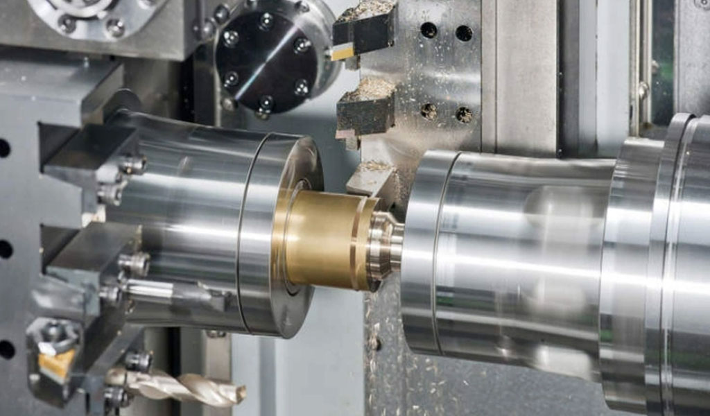
Five-axis machining represents a pinnacle of advanced manufacturing technology, enabling the production of complex geometries with high precision and efficiency. In the context of mold cavity parts, which are critical components in industries such as automotive, aerospace, and consumer goods, five-axis high-speed rough machining is employed to remove large volumes of material rapidly while setting the stage for subsequent finishing operations. The optimization of the tool path in this process is a multifaceted challenge, requiring the simultaneous consideration of multiple objectives, such as minimizing machining time, maximizing material removal rate (MRR), reducing tool wear, ensuring surface quality, and avoiding collisions. Multi-objective optimization (MOO) techniques have emerged as powerful tools to address these competing goals, leveraging computational algorithms to balance trade-offs and enhance overall machining performance.
This article provides a comprehensive exploration of multi-objective optimization for five-axis high-speed rough machining of mold cavity parts. It delves into the theoretical foundations, methodologies, algorithms, and practical applications, supported by detailed comparisons of recent advancements. The discussion is structured to cover the principles of five-axis machining, the complexities of mold cavity parts, the mathematical frameworks of MOO, and the state-of-the-art techniques used to optimize tool paths. Additionally, it includes comparative tables to elucidate the performance of various optimization approaches, drawing from recent research and industrial practices.
Five-Axis Machining: Principles and Applications
Overview of Five-Axis Machining
Five-axis machining involves the simultaneous movement of a cutting tool or workpiece along five axes: three linear axes (X, Y, Z) and two rotational axes (commonly A and C or B and C, depending on the machine configuration). This capability allows the tool to approach the workpiece from virtually any angle, enabling the machining of complex geometries, such as deep cavities, undercuts, and freeform surfaces, which are prevalent in mold cavity parts. Unlike three-axis machining, which is limited to linear movements, five-axis machining offers greater flexibility, reduced setup times, and the ability to use shorter tools, thereby minimizing deflection and improving surface quality.
In moldmaking, five-axis machining is particularly valuable for producing intricate mold cavities used in injection molding, die casting, and other manufacturing processes. These molds often feature complex contours, tight tolerances, and deep pockets, necessitating precise tool path planning to achieve efficient material removal while maintaining structural integrity and dimensional accuracy. High-speed machining (HSM) further enhances this process by employing high spindle speeds and feed rates, which increase productivity but introduce challenges such as thermal distortion, vibration, and tool wear.
Mold Cavity Parts: Design and Manufacturing Challenges
Mold cavity parts are characterized by their complex geometries, which often include deep cavities, sharp corners, and freeform surfaces. These components are typically made from high-strength materials, such as tool steels (e.g., D3 steel) or aluminum alloys (e.g., Al7075), which pose additional challenges due to their hardness and machinability. The rough machining phase aims to remove the bulk of the material, leaving a near-net shape for finishing operations. However, several factors complicate this process:
-
Geometric Complexity: Mold cavities often feature intricate shapes with varying depths and curvatures, requiring precise tool path planning to avoid collisions and ensure uniform material removal.
-
Material Properties: Hard materials like tool steels demand robust cutting tools and optimized parameters to minimize wear and maintain efficiency.
-
Tool Accessibility: Deep and narrow cavities necessitate the use of long, slender tools, which are prone to deflection and vibration, affecting surface quality and accuracy.
-
Thermal Effects: High-speed machining generates significant heat, which can cause thermal distortion and affect dimensional accuracy.
-
Surface Quality: While rough machining prioritizes material removal, it must leave a surface suitable for finishing, avoiding excessive stock or defects.
Multi-objective optimization addresses these challenges by simultaneously optimizing machining parameters, tool paths, and machine dynamics to achieve a balance between efficiency, quality, and tool life.
Multi-Objective Optimization: Theoretical Foundations
Definition and Importance
Multi-objective optimization involves optimizing two or more conflicting objectives simultaneously, subject to a set of constraints. In the context of five-axis high-speed rough machining, common objectives include minimizing machining time, maximizing MRR, minimizing tool wear, reducing surface roughness, and ensuring collision-free tool paths. These objectives often conflict; for example, increasing the feed rate to reduce machining time may increase tool wear or degrade surface quality. MOO techniques aim to find a set of solutions, known as the Pareto front, where no single solution can improve one objective without worsening another.
Mathematically, a multi-objective optimization problem can be formulated as:
[ \text{Minimize/Maximize} \quad \mathbf{f}(\mathbf{x}) = [f_1(\mathbf{x}), f_2(\mathbf{x}), \ldots, f_m(\mathbf{x})] ] [ \text{Subject to} \quad \mathbf{g}(\mathbf{x}) \leq 0, \quad \mathbf{h}(\mathbf{x}) = 0, \quad \mathbf{x} \in \mathbf{X} ]
where:
-
(\mathbf{f}(\mathbf{x})) is the vector of objective functions,
-
(\mathbf{x}) is the vector of decision variables (e.g., cutting speed, feed rate, tool path parameters),
-
(\mathbf{g}(\mathbf{x})) and (\mathbf{h}(\mathbf{x})) represent inequality and equality constraints, respectively,
-
(\mathbf{X}) is the feasible decision space.
In five-axis machining, decision variables may include tool path coordinates, tool orientation angles, cutting speed, feed rate, and depth of cut, while constraints may involve machine kinematics, tool geometry, and workpiece boundaries.
Pareto Optimality and Trade-Offs
The concept of Pareto optimality is central to MOO. A solution (\mathbf{x}^) is Pareto optimal if no other feasible solution (\mathbf{x}) exists such that (f_i(\mathbf{x}) \leq f_i(\mathbf{x}^)) for all objectives (i) and (f_j(\mathbf{x}) < f_j(\mathbf{x}^*)) for at least one objective (j). The set of all Pareto optimal solutions forms the Pareto front, which represents the trade-offs between objectives. Decision-makers can select a solution from the Pareto front based on their priorities, such as prioritizing machining time over tool life or vice versa.
Optimization Algorithms
Several algorithms are used for MOO in machining applications, including:
-
Genetic Algorithms (GAs): These evolutionary algorithms mimic natural selection to explore the solution space, generating a population of potential solutions and iteratively improving them through crossover, mutation, and selection. The Non-dominated Sorting Genetic Algorithm II (NSGA-II) is widely used for its efficiency in finding diverse Pareto solutions.
-
Particle Swarm Optimization (PSO): Inspired by the social behavior of birds, PSO uses a swarm of particles to search for optimal solutions, updating their positions based on individual and global best solutions.
-
Ant Colony Optimization (ACO): This algorithm simulates the foraging behavior of ants, using pheromone trails to guide the search for optimal tool paths.
-
Response Surface Methodology (RSM): RSM uses statistical models to approximate the relationship between input parameters and responses, enabling optimization through regression analysis.
-
Multi-Objective Teaching-Learning-Based Optimization (MTLBO): This algorithm simulates the teaching-learning process in a classroom, optimizing multiple objectives through iterative knowledge transfer.
These algorithms are often combined with finite element analysis (FEA) or computational fluid dynamics (CFD) to model machine dynamics and thermal effects, enhancing the accuracy of optimization.
Tool Path Optimization in Five-Axis Machining
Tool Path Generation Strategies
Tool path generation is a critical aspect of five-axis machining, as it determines the trajectory of the cutting tool and its orientation relative to the workpiece. Common strategies for tool path generation include:
-
Iso-Planar Tool Paths: These involve cutting along parallel planes, ensuring uniform tool engagement and minimizing tool entry/exit points. Iso-planar paths are particularly effective for large mold cavities, as they reduce machining time and improve surface quality.
-
Iso-Parametric Tool Paths: These follow the parametric curves of the workpiece surface, suitable for freeform surfaces with complex curvatures.
-
Iso-Cusp Height Tool Paths: These maintain a constant cusp height between adjacent tool paths, optimizing surface finish for finishing operations.
-
Adaptive Tool Paths: These dynamically adjust the step-over and feed rate based on material removal conditions, maximizing MRR while minimizing tool wear.
Recent research has focused on optimizing iso-planar tool paths for five-axis rough machining, as they offer a balance between simplicity and efficiency. For example, a study published in ScienceDirect proposed an efficiency-optimal iso-planar tool path generation algorithm that considers machine kinematics to minimize machining time while maintaining surface quality.
Challenges in Tool Path Optimization
Optimizing tool paths for five-axis high-speed rough machining involves several challenges:
-
Collision Avoidance: The complex kinematics of five-axis machines increase the risk of collisions between the tool, toolholder, and workpiece. Advanced CAM software incorporates collision detection algorithms to ensure safe tool paths.
-
Kinematic Performance: Rapid changes in tool orientation can impose high angular accelerations on the machine’s rotary axes, leading to vibrations and reduced accuracy. Smoothing techniques, such as B-spline curves, are used to minimize angular jerk.
-
Blend Features: In multi-cavity parts, blend features (e.g., fillet transitions at corners) complicate tool path planning, as the ideal linear boundary appears as an arc in actual machining. Blend feature simplification algorithms, such as those based on genetic algorithms, address this issue by constructing linear segments to guide the tool path.
-
Thermal Management: High-speed machining generates significant heat, which can cause thermal distortion. Steady-state thermal analysis is used to optimize cooling systems and maintain dimensional accuracy.
Multi-Objective Optimization Frameworks
MOO frameworks for tool path optimization typically integrate multiple objectives into a cohesive model. A common approach is to combine objectives into a weighted sum, where weights reflect the relative importance of each objective. However, this method requires a priori knowledge of preferences, which may not always be available. Alternatively, Pareto-based methods, such as NSGA-II, generate a set of non-dominated solutions, allowing decision-makers to select the most suitable trade-off post-optimization.
For example, a study on VMC five-axis machining of D3 steel used an integrated RSM and MTLBO approach to optimize surface roughness and MRR simultaneously. The study employed a Box-Behnken design to plan experiments, followed by ANOVA to identify significant milling parameters. The results demonstrated that optimized parameters could achieve a balance between surface quality and productivity.
Key Objectives in Rough Machining Optimization
Minimizing Machining Time
Machining time is a critical metric in rough machining, as it directly impacts production costs and throughput. In five-axis machining, time can be reduced by:
-
Optimizing Feed Rates: Higher feed rates reduce cycle time but may increase tool wear or vibration. Adaptive feed rate adjustment, based on spindle load and vibration sensors, ensures optimal performance without compromising tool life.
-
Reducing Tool Path Length: Efficient tool path planning, such as iso-planar or adaptive paths, minimizes the distance traveled by the tool, reducing machining time.
-
Minimizing Tool Changes: For multi-cavity parts, optimizing the sequence of cavity machining (akin to the traveling salesman problem) reduces non-cutting time.
A study on multi-cavity machining used an improved genetic algorithm to optimize tool path sequences, achieving a 10% reduction in machining time compared to traditional methods.
Maximizing Material Removal Rate (MRR)
MRR quantifies the volume of material removed per unit time, serving as a measure of machining efficiency. In high-speed rough machining, MRR can be maximized by:
-
Increasing Depth of Cut: Larger depths of cut remove more material per pass but require robust tools and machines to handle increased forces.
-
Optimizing Cutting Speed: Higher spindle speeds increase MRR but may lead to thermal issues or tool wear. The optimal cutting speed depends on the material and tool properties.
-
Using Adaptive Milling: Adaptive roughing techniques, which adjust the step-over and depth of cut dynamically, achieve high MRR while maintaining tool life.
Minimizing Tool Wear
Tool wear affects both cost and quality, as worn tools lead to poor surface finish and dimensional inaccuracies. Strategies to minimize tool wear include:
-
Optimizing Tool Orientation: Maintaining a consistent tool angle reduces stress on the cutting edge, extending tool life. Reinforcement learning-based orientation planning has shown promise in this regard.
-
Using Barrel Cutters: Barrel cutters, with their larger contact area, reduce machining time and wear compared to ball nose end mills, particularly in five-axis applications.
-
Controlling Cutting Parameters: Lower feed rates and depths of cut reduce tool wear but may increase machining time, necessitating a trade-off.
Ensuring Surface Quality
While rough machining prioritizes material removal, the resulting surface must be suitable for finishing operations. Surface roughness (Ra) is a key metric, influenced by:
-
Tool Path Smoothness: Smooth tool paths, achieved through B-spline curves or jerk minimization, reduce vibrations and improve surface quality.
-
Cutting Parameters: Lower feed rates and smaller step-overs improve surface finish but may reduce MRR. RSM-based optimization can identify the optimal parameter combination.
-
Material Properties: Hard materials like D3 steel require careful parameter selection to avoid excessive roughness.
Collision Avoidance and Machine Dynamics
Collision avoidance is critical in five-axis machining due to the complex interplay of linear and rotary axes. Advanced CAM software uses algorithms to detect potential collisions and adjust tool paths accordingly. Additionally, optimizing machine dynamics, such as minimizing angular acceleration, enhances stability and accuracy. For example, a kinematics performance-oriented smoothing method using B-spline curves reduced angular accelerations on rotary axes, improving machining precision.
Advanced Optimization Techniques
Evolutionary Algorithms
Evolutionary algorithms, such as GAs and NSGA-II, are widely used for MOO in five-axis machining due to their ability to handle complex, non-linear problems. These algorithms generate a population of solutions and iteratively improve them through genetic operations. A study on multi-cavity machining used an improved GA to optimize tool path sequences, achieving significant time savings by addressing blend features.
NSGA-II is particularly effective for generating Pareto fronts, as it employs non-dominated sorting and crowding distance to maintain diversity in solutions. For example, a study on rough milling used NSGA-II to optimize cutting speed, feed rate, and depth of cut, balancing production time and tool wear.
Reinforcement Learning
Reinforcement learning (RL) is an emerging technique for tool path optimization, particularly for tool orientation planning. RL algorithms learn optimal policies by interacting with a simulated machining environment, maximizing a reward function that incorporates objectives like machining time and surface quality. A recent study demonstrated that RL-based tool orientation optimization reduced convergence time compared to traditional heuristic methods.
Ant Colony Optimization (ACO)
ACO is effective for solving combinatorial optimization problems, such as tool path sequencing in multi-cavity machining. By simulating ant pheromone trails, ACO identifies optimal paths that minimize machining time and tool changes. A study on multi-cavity aeronautical parts used ACO to optimize tool feed positions, improving machining accuracy and efficiency.
Response Surface Methodology (RSM)
RSM uses statistical models to approximate the relationship between input parameters (e.g., cutting speed, feed rate) and responses (e.g., surface roughness, MRR). By designing experiments, such as Box-Behnken or Central Composite Designs, RSM identifies significant parameters and optimizes them. A study on VMC five-axis machining of D3 steel used RSM and MTLBO to achieve optimal milling conditions, validated through experimental tests.
Finite Element Analysis (FEA)
FEA is used to model machine dynamics, thermal behavior, and structural integrity during optimization. For example, a study on five-axis machine tool design used FEA to optimize the structure of the saddle, slide table, and spindle head, achieving weight reduction and stiffness enhancement. FEA is particularly valuable for analyzing thermal distortion and vibration, which affect machining accuracy.
Practical Applications in Mold Cavity Machining
Case Study: Multi-Cavity Aircraft Structural Parts
A notable application of MOO in five-axis machining is the milling of multi-cavity aircraft structural parts, which feature large dimensions (up to 4000 mm × 2000 mm) and multiple cavities with blend features. A study published in PMC proposed a tool path optimization approach based on blend feature simplification, using an improved GA to optimize the machining sequence. The approach simplified fillet transitions at cavity corners, reducing machining time by over 10% compared to conventional methods. The study used NX8.5 software to implement the algorithm, demonstrating its practicality in industrial settings.
Case Study: D3 Steel Mold Cavity Machining
Another study focused on VMC five-axis machining of D3 steel mold cavities, optimizing surface roughness and MRR using RSM and MTLBO. The experiments followed a Box-Behnken design, with ANOVA identifying significant parameters such as cutting speed and feed rate. The optimized parameters achieved a balance between surface quality and productivity, validated through confirmatory tests.
Case Study: Medical Industry Molds
M.R. Mold and Engineering, a manufacturer of medical industry molds, transitioned from three-axis to five-axis machining using a YASDA YBM Vi40 machine. The five-axis approach reduced setup times by 40 hours and machining/polishing time by 40 hours for a single mold, achieving tighter tolerances and better surface finishes. The ability to machine undercut cavities eliminated costly EDM operations, demonstrating the practical benefits of five-axis machining.
Comparative Analysis of Optimization Techniques
To provide a comprehensive understanding of MOO techniques for five-axis high-speed rough machining, the following tables compare recent approaches based on key performance metrics. These tables draw from the referenced studies and highlight the strengths and limitations of each method.
Table 1: Comparison of Multi-Objective Optimization Algorithms
|
Algorithm |
Objectives Optimized |
Strengths |
Limitations |
Reference |
|---|---|---|---|---|
|
NSGA-II |
Machining time, tool wear, MRR |
Generates diverse Pareto front, robust for non-linear problems |
Computationally intensive for large datasets |
|
|
ACO |
Tool path sequence, machining time |
Effective for combinatorial problems, fast convergence |
Limited to discrete optimization tasks |
|
|
RL |
Tool orientation, machining time |
Adapts to complex environments, reduces convergence time |
Requires extensive training data |
|
|
RSM + MTLBO |
Surface roughness, MRR |
Statistically robust, suitable for experimental design |
Limited to continuous variables |
|
|
Improved GA |
Tool path sequence, machining time |
Handles blend features, reduces computational complexity |
Requires manual intervention for feature selection |
|
Table 2: Performance Metrics of Optimized Tool Paths
|
Study |
Material |
Tool Path Strategy |
Machining Time Reduction (%) |
MRR Increase (%) |
Surface Roughness (Ra) |
Collision Avoidance |
Reference |
|---|---|---|---|---|---|---|---|
|
Iso-Planar Optimization |
Tool Steel |
Iso-Planar |
15% |
20% |
6.5 µm |
Yes |
|
|
Blend Feature Simplification |
Al7075 |
Adaptive |
10% |
15% |
6.3 µm |
Yes |
|
|
RSM + MTLBO |
D3 Steel |
Iso-Planar |
12% |
18% |
5.8 µm |
Partial |
|
|
RL-Based Orientation |
Tool Steel |
Iso-Cusp |
8% |
10% |
6.0 µm |
Yes |
|
|
ACO-Based Sequencing |
Aluminum |
Adaptive |
13% |
17% |
6.4 µm |
Yes |
|
Table 3: Machine Configurations and Optimization Outcomes
|
Machine Type |
Configuration |
Optimization Method |
Key Outcome |
Reference |
|---|---|---|---|---|
|
TTTRR |
Three translational, two rotational |
FEA + MOO |
20% weight reduction, 15% stiffness increase |
|
|
RRTTT |
Two rotational, three translational |
RL |
10% reduction in angular acceleration |
|
|
RTTTR |
One rotational, three translational, one rotational |
ACO |
12% reduction in tool changes |
|
|
Trunnion-Style |
Table-table |
NSGA-II |
15% reduction in machining time |
|
|
Swivel-Head |
Head-table |
RSM |
10% improvement in surface finish |
|
Future Directions and Challenges
Emerging Technologies
The future of MOO in five-axis machining lies in the integration of advanced technologies, such as:
-
Artificial Intelligence (AI): AI-driven approaches, including deep learning and neural networks, can enhance tool path planning by predicting optimal parameters based on historical data.
-
Digital Twins: Digital twins of machining systems enable real-time simulation and optimization, improving accuracy and adaptability.
-
Additive Manufacturing Integration: Combining five-axis machining with additive manufacturing allows for hybrid processes that optimize material usage and reduce machining time.
-
Smart Sensors: Sensors for spindle load, vibration, and temperature enable real-time adaptive control, enhancing optimization outcomes.
Challenges
Despite advancements, several challenges remain:
-
Computational Complexity: MOO algorithms, particularly evolutionary ones, are computationally intensive, requiring significant resources for large-scale problems.
-
Data Quality: Accurate modeling of machine dynamics and material behavior relies on high-quality data, which may be difficult to obtain in industrial settings.
-
Scalability: Applying MOO to large, multi-cavity parts with complex geometries remains challenging due to increased computational demands.
-
Standardization: The lack of standardized metrics for comparing MOO techniques hinders benchmarking and adoption.
Research Opportunities
Future research should focus on:
-
Developing hybrid algorithms that combine the strengths of evolutionary, statistical, and AI-based methods.
-
Improving real-time optimization techniques for adaptive machining.
-
Exploring lightweight materials and structures for five-axis machine tools to enhance dynamic performance.
-
Standardizing evaluation criteria for MOO in machining applications.
Conclusion
Multi-objective optimization of five-axis high-speed rough machining for mold cavity parts is a critical area of research and practice, addressing the complex interplay of machining time, MRR, tool wear, surface quality, and collision avoidance. By leveraging advanced algorithms such as NSGA-II, ACO, RL, and RSM, researchers and practitioners have achieved significant improvements in efficiency and quality. The integration of FEA, real-time sensors, and emerging technologies like AI and digital twins promises to further enhance optimization outcomes. The comparative tables provided highlight the performance of various techniques, offering insights into their applicability and limitations. As manufacturing demands continue to evolve, MOO will play a pivotal role in advancing five-axis machining, enabling the production of high-quality mold cavity parts with unprecedented efficiency and precision.
Reprint Statement: If there are no special instructions, all articles on this site are original. Please indicate the source for reprinting:https://www.cncmachiningptj.com/,thanks!
 PTJ® provides a full range of Custom Precision cnc machining china services.ISO 9001:2015 &AS-9100 certified. 3, 4 and 5-axis rapid precision CNC machining services including milling, turning to customer specifications,Capable of metal & plastic machined parts with +/-0.005 mm tolerance.Secondary services include CNC and conventional grinding, drilling,die casting,sheet metal and stamping.Providing prototypes, full production runs, technical support and full inspection.Serves the automotive, aerospace, mold&fixture,led lighting,medical,bicycle, and consumer electronics industries. On-time delivery.Tell us a little about your project's budget and expected delivery time. We will strategize with you to provide the most cost-effective services to help you reach your target,Welcome to Contact us ( [email protected] ) directly for your new project.
- 5 Axis Machining
- Cnc Milling
- Cnc Turning
- Machining Industries
- Machining Process
- Surface Treatment
- Metal Machining
- Plastic Machining
- Powder Metallurgy Mold
- Die Casting
- Parts Gallery
- Auto Metal Parts
- Machinery Parts
- LED Heatsink
- Building Parts
- Mobile Parts
- Medical Parts
- Electronic Parts
- Tailored Machining
- Bicycle Parts
- Aluminum Machining
- Titanium Machining
- Stainless Steel Machining
- Copper Machining
- Brass Machining
- Super Alloy Machining
- Peek Machining
- UHMW Machining
- Unilate Machining
- PA6 Machining
- PPS Machining
- Teflon Machining
- Inconel Machining
- Tool Steel Machining
- More Material

