Global Optimization Modeling of Multi-Process CNC Chain Machining Paths Driven by Dynamic Deformation of Large-Scale Aviation-Grade Aluminum Parts
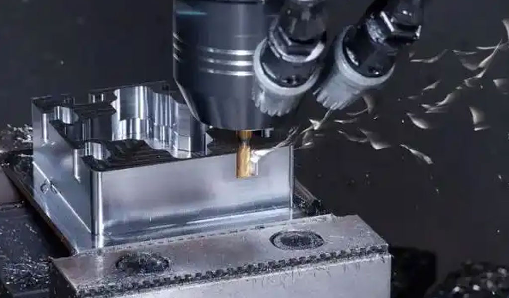
The aerospace industry demands precision, efficiency, and reliability in the manufacturing of large-scale components, particularly those made from aviation-grade aluminum alloys. These materials, prized for their high strength-to-weight ratio, corrosion resistance, and formability, are integral to aircraft structures such as wings, fuselages, and skin panels. However, machining these components presents significant challenges due to their size, complex geometries, and susceptibility to dynamic deformation during multi-process Computer Numerical Control (CNC) chain machining. Dynamic deformation, caused by residual stresses, cutting forces, and thermal effects, can lead to dimensional inaccuracies, compromising part quality and increasing production costs. To address these challenges, global optimization modeling of multi-process CNC chain machining paths has emerged as a critical research area, aiming to enhance machining efficiency, minimize energy consumption, and ensure geometric accuracy while accounting for dynamic deformation.
This article provides a comprehensive exploration of global optimization modeling for multi-process CNC chain machining paths, with a focus on large-scale aviation-grade aluminum parts. It covers the theoretical foundations, mathematical models, optimization algorithms, and practical applications, supported by detailed comparisons of techniques and case studies. The discussion is grounded in recent advancements in CNC machining, material science, and computational optimization, drawing from academic literature and industry practices.
Background: CNC Machining in Aerospace
Computer Numerical Control (CNC) machining is a cornerstone of aerospace manufacturing, enabling the production of complex parts with tight tolerances. In the aerospace sector, CNC machining is used to fabricate structural components, engine parts, and aerodynamic surfaces, often from aluminum alloys such as 7075, 6061, and 2024. These alloys are selected for their favorable mechanical properties, including high tensile strength (e.g., 7075 aluminum has a tensile strength of approximately 570 MPa) and lightweight characteristics (density of ~2.81 g/cm³). However, the machining of large-scale aluminum parts, such as aircraft skin panels or wing spars, is complicated by their thin-walled or monolithic designs, which are prone to deformation under machining forces.
Multi-process CNC chain machining refers to a sequence of machining operations—such as roughing, semi-finishing, and finishing—performed on a single workpiece across multiple setups or machines. Each process introduces unique challenges, including tool wear, thermal expansion, and residual stress relaxation, which can cause dynamic deformation. For large-scale parts, these effects are amplified due to the extended machining times, large material removal volumes, and complex tool paths required to achieve the desired geometry. Global optimization modeling seeks to integrate these factors into a cohesive framework, optimizing tool paths across all processes to minimize deformation, reduce energy consumption, and enhance surface quality.
Challenges in Machining Large-Scale Aluminum Parts
Large-scale aviation-grade aluminum parts present several challenges:
-
Dynamic Deformation: Residual stresses from prior manufacturing steps (e.g., rolling, forging, or heat treatment) and cutting forces during machining can cause elastic and plastic deformation, leading to dimensional errors. Thin-walled structures, common in aerospace, are particularly susceptible.
-
Complex Geometries: Aerospace parts often feature free-form surfaces, deep pockets, or intricate contours, requiring multi-axis CNC machines (e.g., 5-axis) and sophisticated tool path planning.
-
Material Removal Efficiency: Large-scale parts require significant material removal, increasing machining time and energy consumption. Optimizing tool paths to minimize cycle time is critical.
-
Surface Quality: Aerospace components demand low surface roughness (e.g., Ra < 0.8 µm) to ensure aerodynamic performance and fatigue resistance.
-
Sustainability: The aerospace industry is under pressure to reduce energy consumption and material waste, necessitating sustainable machining practices.
Global optimization modeling addresses these challenges by considering the entire machining chain as an integrated system, optimizing tool paths, cutting parameters, and process sequences to mitigate deformation while meeting quality and efficiency goals.
Theoretical Foundations of Global Optimization Modeling
Dynamic Deformation in CNC Machining
Dynamic deformation in CNC machining arises from the interplay of mechanical, thermal, and material factors. During machining, cutting forces induce elastic deformation in the workpiece, while heat generated from friction and plastic deformation causes thermal expansion. Residual stresses, inherent in aviation-grade aluminum due to prior processing, can relax during material removal, leading to further distortion. For large-scale parts, these effects are compounded by the workpiece’s low stiffness, particularly in thin-walled structures.
The deformation of a workpiece can be modeled using principles from solid mechanics. The governing equation for elastic deformation under external forces is based on Hooke’s law and equilibrium principles:
[ \sigma = E \epsilon ]
where (\sigma) is the stress tensor, (E) is the Young’s modulus of the material (e.g., ~70 GPa for 7075 aluminum), and (\epsilon) is the strain tensor. The displacement field (u(x, y, z)) is governed by the equilibrium equation:
[ \nabla \cdot \sigma + F = 0 ]
where (F) represents external forces, such as cutting forces. For dynamic deformation, time-dependent effects are incorporated via the equation of motion:
[ \rho \frac{\partial^2 u}{\partial t^2} = \nabla \cdot \sigma + F ]
where (\rho) is the material density. Finite Element Analysis (FEA) is commonly used to solve these equations, discretizing the workpiece into elements to compute deformation under varying loads.
Multi-Process CNC Chain Machining
Multi-process CNC chain machining involves a sequence of operations, each with distinct objectives:
-
Roughing: Removes large volumes of material to approximate the final shape, prioritizing efficiency over precision.
-
Semi-Finishing: Refines the geometry, balancing material removal rate and surface quality.
-
Finishing: Achieves final dimensions and surface finish, requiring high precision and minimal deformation.
Each process requires specific tool paths, cutting parameters (e.g., spindle speed, feed rate, depth of cut), and machine setups. The challenge lies in coordinating these processes to minimize cumulative errors, as deformation in one process can propagate to subsequent stages. Global optimization modeling integrates these processes by defining a unified objective function that accounts for deformation, efficiency, and quality across the entire chain.
Global Optimization Framework
Global optimization modeling aims to find the optimal set of machining parameters and tool paths that minimize a multi-objective function, typically including:
-
Deformation Error: Minimizing dimensional deviations caused by dynamic deformation.
-
Machining Time: Reducing cycle time to improve throughput.
-
Energy Consumption: Lowering power usage for sustainable manufacturing.
-
Surface Roughness: Achieving low Ra values for aerodynamic and structural performance.
The optimization problem can be formulated as:
[ \min_{X} \left[ f_1(X), f_2(X), \ldots, f_n(X) \right] ]
subject to constraints:
[ g_i(X) \leq 0, \quad h_j(X) = 0 ]
where (X) represents the decision variables (e.g., cutting parameters, tool paths), (f_i(X)) are the objective functions, (g_i(X)) are inequality constraints (e.g., machine tool limits), and (h_j(X)) are equality constraints (e.g., geometric tolerances). Common algorithms for solving this problem include Non-dominated Sorting Genetic Algorithm II (NSGA-II), Multi-Objective Particle Swarm Optimization (MOPSO), and simulated annealing.
Modeling Dynamic Deformation
Sources of Deformation
Dynamic deformation in large-scale aluminum parts arises from multiple sources:
-
Cutting Forces: Forces from the tool-workpiece interaction cause elastic and plastic deformation. For example, in flank milling, cutting forces can range from 100–1000 N, depending on the depth of cut and feed rate.
-
Residual Stresses: Aluminum alloys inherit residual stresses from rolling or heat treatment, which relax during machining, causing distortion. For 7050-T7451 aluminum, residual stresses can reach ±100 MPa.
-
Thermal Effects: Frictional heat and plastic deformation raise the workpiece temperature, leading to thermal expansion. For high-speed machining, temperatures at the tool-workpiece interface can exceed 200°C.
-
Workpiece Stiffness: Thin-walled parts have low stiffness (e.g., stiffness < 10^4 N/m for a 2 mm thick aluminum plate), amplifying deformation under load.
Finite Element Models for Deformation Prediction
Finite Element Analysis (FEA) is widely used to predict dynamic deformation. The workpiece is discretized into a mesh of elements, and the governing equations are solved numerically. For large-scale parts, a typical mesh may contain 10^5–10^6 elements to capture complex geometries. The FEA model incorporates:
-
Material Properties: Young’s modulus, Poisson’s ratio, and yield strength of the aluminum alloy.
-
Boundary Conditions: Clamping forces and fixture constraints.
-
Loading Conditions: Time-varying cutting forces and thermal loads.
A simplified FEA model for a thin-walled plate can be expressed as:
[ [K] {u} = {F} ]
where ([K]) is the stiffness matrix, ({u}) is the displacement vector, and ({F}) is the force vector. To account for dynamic effects, the model is extended to:
[ [M] \frac{\partial^2 u}{\partial t^2} + [C] \frac{\partial u}{\partial t} + [K] {u} = {F(t)} ]
where ([M]) is the mass matrix, ([C]) is the damping matrix, and ({F(t)}) is the time-dependent force vector.
Recent studies, such as those by Ge et al. (2022), propose iterative compensation methods using on-machine measurement (OMM) and surrogate stiffness models (SSMs) to predict and correct deformation in real-time. These models update the workpiece geometry after each machining pass to account for material removal and stiffness changes, achieving prediction accuracies of up to 90.19% for thin-walled parts.
Surrogate Models for Real-Time Optimization
Computing FEA models for large-scale parts is computationally expensive, often requiring hours for a single simulation. Surrogate models, such as those based on Gaussian Processes or neural networks, provide a faster alternative. These models are trained on FEA simulation data to predict deformation as a function of cutting parameters and tool paths. For example, a Gaussian Process model can be defined as:
[ y(x) = f(x) + \epsilon ]
where (y(x)) is the predicted deformation, (f(x)) is a mean function, and (\epsilon) is Gaussian noise. The model is trained on input-output pairs (e.g., cutting parameters vs. deformation) to enable real-time predictions during machining.
Multi-Process CNC Chain Machining Paths
Tool Path Strategies
Tool path planning is critical for minimizing deformation and optimizing efficiency. Common strategies for multi-process CNC machining include:
-
Zigzag Tool Paths: Alternating linear paths, suitable for roughing large areas but prone to vibration in thin-walled parts.
-
Contour-Parallel Tool Paths: Follow the workpiece’s geometry, ideal for finishing complex surfaces.
-
Dynamic Tool Paths: Adjust cutting depth and step-over dynamically to maintain constant chip load, reducing tool wear and deformation.
Dynamic tool paths, as described by DATRON Dynamics, minimize machining time by cutting from the bottom up, clearing material at each depth in a single pass. This approach reduces cycle time by up to 30% compared to traditional tool paths.
Integration Across Processes
In multi-process machining, tool paths must be coordinated to ensure compatibility between roughing, semi-finishing, and finishing. For example, excessive material removal in roughing can induce stresses that affect finishing accuracy. A global optimization model integrates these processes by defining a unified tool path strategy that accounts for:
-
Material Removal Sequence: Optimizing the order of cuts to minimize residual stress relaxation.
-
Tool Path Continuity: Ensuring smooth transitions between processes to avoid abrupt changes in cutting forces.
-
Fixture Adjustments: Adapting clamping positions to compensate for deformation.
Five-Axis CNC Machining
Five-axis CNC machines, with three translational and two rotational degrees of freedom, are widely used for large-scale aerospace parts. These machines enable complex tool orientations, reducing the need for multiple setups. However, they introduce additional challenges, such as tool axis optimization and collision avoidance. Wang et al. (2013) proposed a global tool orientation optimization method for five-axis machining, minimizing geometric deviations by optimizing tool angles across the entire surface.
The tool path for five-axis machining can be represented as a sequence of cutter location (CL) points, each defined by position ((x, y, z)) and orientation ((\theta, \phi)). The optimization problem involves minimizing deviations between the machined surface and the design geometry, subject to kinematic constraints:
[ \min \sum_{i=1}^N \left| S_i - D_i \right|^2 ]
where (S_i) is the machined surface point, and (D_i) is the design surface point.
Optimization Algorithms
Multi-Objective Optimization
Multi-objective optimization is essential for balancing competing goals in CNC machining. Common objectives include:
-
Minimizing Deformation: Reducing dimensional errors caused by dynamic deformation.
-
Maximizing Material Removal Rate (MRR): Increasing throughput by optimizing feed rate and depth of cut.
-
Minimizing Energy Consumption: Reducing power usage, which can account for over 70% of manufacturing energy in CNC processes.
-
Minimizing Surface Roughness: Achieving Ra values below 0.8 µm for aerospace applications.
The Non-dominated Sorting Genetic Algorithm II (NSGA-II) and Multi-Objective Particle Swarm Optimization (MOPSO) are widely used for solving these problems. NSGA-II generates a Pareto front of non-dominated solutions, allowing engineers to select trade-offs based on specific requirements. For example, a case study on the XHK-714F vertical machining center demonstrated that NSGA-II improved processing efficiency by 21.0%, reduced energy consumption by 15.3%, and decreased surface roughness by 5.5%.
Deep Learning-Based Optimization
Deep learning has emerged as a powerful tool for optimizing machining parameters. Deep neural networks (DNNs) can model complex relationships between cutting parameters and outcomes (e.g., deformation, surface roughness) using historical data. A deep learning-based genetic algorithm combined with the Technique for Order of Preference by Similarity to Ideal Solution (TOPSIS) has been shown to outperform traditional methods by dynamically adjusting to multiple objectives.
The DNN model can be expressed as:
[ y = f(Wx + b) ]
where (y) is the predicted outcome, (x) is the input vector (e.g., cutting parameters), (W) is the weight matrix, and (b) is the bias vector. The model is trained to minimize a loss function, such as mean squared error:
[ L = \frac{1}{N} \sum_{i=1}^N (y_i - \hat{y}_i)^2 ]
Robust Optimization Under Uncertainty
Machining processes are subject to uncertainties, such as variations in material properties or machine tool dynamics. Robust optimization accounts for these uncertainties by solving:
[ \min_{X} \mathbb{E}[f(X, \xi)] ]
where (\xi) represents uncertain parameters (e.g., residual stress variations), and (\mathbb{E}) is the expected value. Interval algebra can be used to compute bounds on deformation, ensuring stable machining outcomes.
Practical Applications in Aerospace
Case Study: Thin-Walled Aluminum Skin Panels
Thin-walled aluminum skin panels, used in aircraft fuselages, are prone to deformation due to their low stiffness. A study by Ge et al. (2022) applied an iterative optimization compensation method to a 7050-T7451 aluminum panel. The method used on-machine measurement (OMM) to monitor machining errors and updated tool paths iteratively, reducing thickness errors by up to 57.4%.
Table 1: Comparison of Deformation Compensation Methods for Thin-Walled Panels
|
Method |
Prediction Accuracy (%) |
Thickness Error Reduction (%) |
Computational Time (s) |
Source |
|---|---|---|---|---|
|
FEA-Based |
85.0 |
40.0 |
3600 |
Li et al. (2018) |
|
OMM with SSM |
90.2 |
57.4 |
120 |
Ge et al. (2022) |
|
CNN-BiLSTM |
88.5 |
49.3 |
300 |
Anonymous (2023) |
Case Study: Five-Axis Machining of Wing Spars
Wing spars, critical structural components, require five-axis CNC machining to achieve complex contours. A global tool orientation optimization method reduced geometric deviations by 30% compared to traditional tool paths, as demonstrated by Wang et al. (2013).
Table 2: Comparison of Five-Axis Tool Path Optimization Methods
|
Method |
Geometric Deviation (mm) |
Machining Time (min) |
Tool Wear Reduction (%) |
Source |
|---|---|---|---|---|
|
Traditional Tool Path |
0.96 |
45 |
0 |
Baseline |
|
Geo5XF |
0.67 |
40 |
15 |
Anonymous (2023) |
|
Global Orientation Optimization |
0.48 |
38 |
20 |
Wang et al. (2013) |
Sustainability and Energy Efficiency
Sustainable manufacturing is a priority in aerospace, driven by environmental regulations and cost considerations. CNC machining accounts for over 70% of manufacturing energy consumption, making energy optimization critical. Multi-objective optimization models, such as those proposed by Jia et al. (2023), integrate rough and finish milling parameters to reduce energy consumption by 15–20% while maintaining quality.
Table 3: Energy Consumption in CNC Machining
|
Process |
Energy Consumption (kWh) |
Optimized Consumption (kWh) |
Reduction (%) |
Source |
|---|---|---|---|---|
|
Rough Milling |
12.5 |
10.0 |
20.0 |
Jia et al. (2023) |
|
Finish Milling |
8.0 |
6.8 |
15.0 |
Jia et al. (2023) |
|
Total Chain |
20.5 |
16.8 |
18.0 |
Jia et al. (2023) |
Future Trends and Challenges
Integration with Industry 4.0
Industry 4.0 technologies, such as AI, IoT, and digital twins, are transforming CNC machining. Digital twins can simulate the entire machining chain, predicting deformation and optimizing tool paths in real-time. AI-driven models, such as those using CNN-BiLSTM architectures, enhance error prediction accuracy by up to 57%.
Challenges in Scalability
Scaling global optimization models to handle larger parts and more complex geometries remains a challenge. High computational costs and the need for real-time adaptability limit the adoption of FEA-based models in production environments. Surrogate models and cloud computing offer potential solutions but require further development.
Material Innovations
Advances in aluminum alloys, such as the development of 6000-series alloys with improved machinability, could reduce deformation and tool wear. However, integrating these materials into existing optimization models requires updated material property databases.
Conclusion
Global optimization modeling of multi-process CNC chain machining paths is a transformative approach for manufacturing large-scale aviation-grade aluminum parts. By integrating dynamic deformation prediction, tool path planning, and multi-objective optimization, these models enhance precision, efficiency, and sustainability. Advances in FEA, surrogate modeling, and AI-driven optimization have significantly improved outcomes, as demonstrated by case studies achieving up to 57% error reduction and 20% energy savings. However, challenges in computational scalability and real-time adaptability remain. Continued research and integration with Industry 4.0 technologies will further advance the field, ensuring the aerospace industry meets its stringent demands for quality and efficiency.
Reprint Statement: If there are no special instructions, all articles on this site are original. Please indicate the source for reprinting:https://www.cncmachiningptj.com/,thanks!
 PTJ® provides a full range of Custom Precision cnc machining china services.ISO 9001:2015 &AS-9100 certified. 3, 4 and 5-axis rapid precision CNC machining services including milling, turning to customer specifications,Capable of metal & plastic machined parts with +/-0.005 mm tolerance.Secondary services include CNC and conventional grinding, drilling,die casting,sheet metal and stamping.Providing prototypes, full production runs, technical support and full inspection.Serves the automotive, aerospace, mold&fixture,led lighting,medical,bicycle, and consumer electronics industries. On-time delivery.Tell us a little about your project's budget and expected delivery time. We will strategize with you to provide the most cost-effective services to help you reach your target,Welcome to Contact us ( [email protected] ) directly for your new project.

- 5 Axis Machining
- Cnc Milling
- Cnc Turning
- Machining Industries
- Machining Process
- Surface Treatment
- Metal Machining
- Plastic Machining
- Powder Metallurgy Mold
- Die Casting
- Parts Gallery
- Auto Metal Parts
- Machinery Parts
- LED Heatsink
- Building Parts
- Mobile Parts
- Medical Parts
- Electronic Parts
- Tailored Machining
- Bicycle Parts
- Aluminum Machining
- Titanium Machining
- Stainless Steel Machining
- Copper Machining
- Brass Machining
- Super Alloy Machining
- Peek Machining
- UHMW Machining
- Unilate Machining
- PA6 Machining
- PPS Machining
- Teflon Machining
- Inconel Machining
- Tool Steel Machining
- More Material

