Research on Linkage Control Technology, Nano-Scale CNC Machining Error Modeling, and Magnetorheological Polishing for Ultra-Precision Aluminum Optical Components
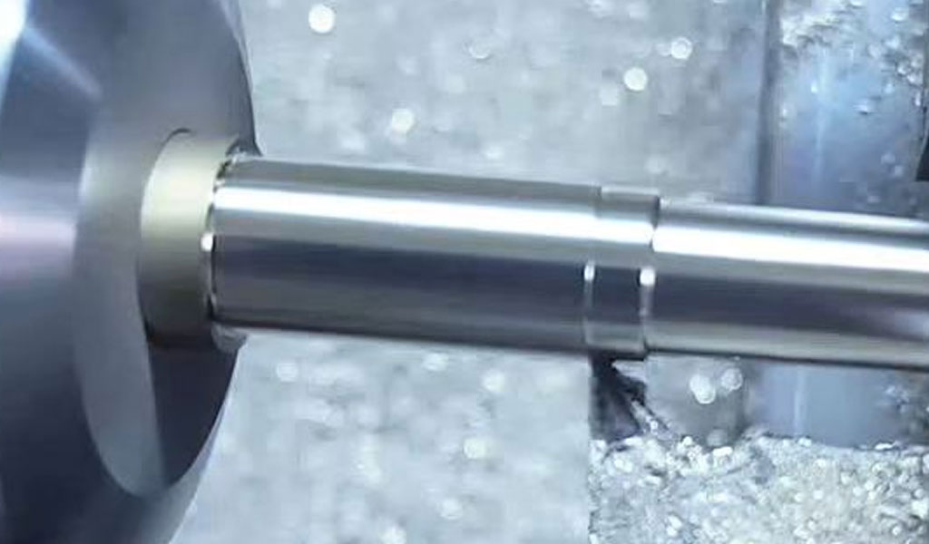
Ultra-precision machining plays a pivotal role in the fabrication of high-performance optical components, particularly those made from aluminum, which are widely used in aerospace, defense, and high-power laser systems due to their lightweight properties, high thermal conductivity, and excellent machinability. The demand for optical surfaces with nanometer-scale roughness and sub-micrometer form accuracy has driven advancements in computer numerical control (CNC) machining, error modeling, and polishing technologies. Among these, linkage control technology and magnetorheological polishing (MRF) have emerged as critical methodologies for achieving the stringent tolerances required in ultra-precision aluminum optical components. This article provides a comprehensive review of the state-of-the-art research in linkage control technology, nano-scale CNC machining error modeling, and MRF, focusing on their application to aluminum optical components. It explores the theoretical foundations, technological advancements, experimental validations, and future directions, supported by detailed comparative analyses.
Fundamentals of Ultra-Precision Machining
Definition and Importance
Ultra-precision machining refers to manufacturing processes capable of producing components with surface roughness in the nanometer range and form accuracies in the sub-micrometer range. These processes are essential for optical components, where surface quality directly impacts performance, such as in minimizing light scattering and ensuring high laser damage thresholds. Aluminum, due to its favorable mechanical and thermal properties, is a preferred material for optical mirrors and lenses in applications like telescopes, laser systems, and satellite optics. However, its softness and susceptibility to machining-induced defects necessitate advanced control and finishing techniques.
Challenges in Aluminum Optical Component Fabrication
Aluminum optical components pose unique challenges in ultra-precision machining. The material’s ductility leads to issues such as burr formation, tool wear, and surface defects like scratches and micro-waviness. Additionally, achieving nanometer-scale surface finishes requires precise control over machining parameters and compensation for errors introduced by machine dynamics, thermal effects, and tool-workpiece interactions. Linkage control technology and MRF address these challenges by enhancing machine precision and providing deterministic polishing methods, respectively.
Linkage Control Technology in Nano-Scale CNC Machining
Principles of Linkage Control
Linkage control technology in CNC machining involves the coordinated motion of multiple machine axes to achieve complex tool paths and maintain high precision. In nano-scale CNC machining, linkage control ensures that the tool follows the desired trajectory with minimal deviation, critical for producing freeform and aspheric optical surfaces. This technology integrates advanced control algorithms, high-resolution feedback systems, and multi-axis synchronization to mitigate errors caused by machine dynamics and external disturbances.
Multi-Axis Synchronization
Modern ultra-precision CNC machines often employ five-axis or higher configurations to machine complex geometries. Synchronization of translational (X, Y, Z) and rotational (A, B, C) axes is crucial to maintain tool-workpiece alignment, especially for high-steepness aspheric surfaces. Research has shown that advanced linkage control systems, such as those incorporating virtual-axis technology, can extend the machining range without requiring additional mechanical axes, thus improving efficiency and precision. For instance, virtual-axis technology compensates for steep curvature changes by adjusting the polishing wheel’s arc segment, reducing the dependency on large swing angles.
Control Algorithms
Control algorithms, such as proportional-integral-derivative (PID) controllers, adaptive control, and model predictive control (MPC), are employed to enhance linkage accuracy. Adaptive control adjusts machining parameters in real-time based on sensor feedback, while MPC optimizes tool paths by predicting future states of the machine. These algorithms minimize errors due to backlash, hysteresis, and thermal expansion, ensuring nanometer-level positioning accuracy.
Case Study: Virtual-Axis Technology
A notable advancement in linkage control is the use of virtual-axis technology in MRF, as demonstrated by QED Technologies. This approach allows the polishing wheel to adapt to high-steepness surfaces by simulating additional axes through software, reducing mechanical complexity. Experimental results on a 100 mm aspheric fused silica optic showed a peak-to-valley (PV) error reduction from 189.2 nm to 24.85 nm, highlighting the efficacy of this method in ultra-precision applications.
Nano-Scale CNC Machining Error Modeling
Sources of Machining Errors
Nano-scale CNC machining errors arise from multiple sources, including geometric errors (e.g., axis misalignment), kinematic errors (e.g., tool path deviations), thermal-induced errors, and dynamic errors (e.g., vibrations). For aluminum optical components, additional errors stem from material anisotropy, tool wear, and cutting forces. Understanding and modeling these errors are critical for developing compensation strategies.
Error Modeling Techniques
Geometric Error Modeling
Geometric error modeling involves quantifying deviations in machine tool components, such as spindle runout and guideway straightness. Techniques like laser interferometry and capacitive sensors, with resolutions down to 1 nm, are used to measure these errors. For example, the Renishaw XL-80 laser interferometer achieves 0.1 μm/m angular error resolution, enabling precise calibration of ultra-precision machine tools (UPMTs).
Kinematic Error Modeling
Kinematic error modeling focuses on the relative motion between the tool and workpiece. Homogeneous transformation matrices (HTMs) are commonly used to describe the cumulative effect of axis misalignments. Recent studies have developed advanced kinematic models for five-axis UPMTs, accounting for coupled error components at the nanoscale.
Thermal Error Modeling
Thermal errors, caused by temperature gradients in the machine or workpiece, are significant in aluminum machining due to the material’s high thermal conductivity. Finite element analysis (FEA) is employed to simulate thermal expansion and contraction, enabling predictive compensation. For instance, thermal control systems with ±0.5°C accuracy are integrated into modern UPMTs like the Cranfield Box grinding machine.
Dynamic Error Modeling
Dynamic errors result from vibrations and machine tool dynamics. Frequency-domain analysis and finite element modeling are used to identify resonant frequencies and dampen vibrations. Active damping systems and anti-vibration mounts with natural frequencies above 2 Hz are employed to isolate external disturbances.
Error Compensation Strategies
Error compensation involves adjusting tool paths and machining parameters to counteract modeled errors. Techniques include:
-
Real-Time Compensation: Using feedback from high-resolution encoders to adjust tool positions dynamically.
-
Pre-Compensation: Modifying NC code based on predicted error models before machining.
-
Iterative Compensation: Refining tool paths through multiple machining passes based on metrology feedback.
A study on a five-axis CNC machining center integrated with MRF demonstrated a reduction in root-mean-square (RMS) error from 46.8 nm to 5.5 nm by compensating for positioning and removal function errors.
Magnetorheological Polishing (MRF) for Ultra-Precision Finishing
Principles of MRF
Magnetorheological finishing (MRF) is a deterministic polishing process that uses a magnetorheological fluid (MRF) containing magnetic particles, abrasives, and a carrier liquid. Under a magnetic field, the fluid solidifies into a compliant polishing tool that conforms to the workpiece surface, enabling precise material removal with minimal subsurface damage. MRF is particularly effective for aluminum optical components, achieving surface roughness as low as 0.57 nm Ra.
MRF Process Mechanics
The MRF process involves a rotating wheel or other tool geometry (e.g., ball-type, cluster-type) that delivers the MR fluid to the workpiece surface. The magnetic field induces a gradient that stiffens the fluid, creating a shear force that removes material. The Preston equation governs material removal:
[ R = k \cdot P \cdot V ]
where ( R ) is the material removal rate, ( k ) is the Preston coefficient, ( P ) is the polishing pressure, and ( V ) is the relative velocity between the tool and workpiece.
Advancements in MRF Technology
Wheel-Type MRF
Wheel-type MRF, pioneered by the University of Rochester’s Center for Optics Manufacturing, uses a rotating wheel to deliver the MR fluid. It is effective for planar and low-curvature surfaces, achieving PV values below 50 nm. Recent innovations include inverted wheel designs for improved accessibility to complex geometries.
Cluster-Type and Ball-Type MRF
Cluster-type MRF employs multiple polishing spots for high-efficiency processing, while ball-type MRF uses a spherical tool for freeform surfaces. These methods enhance flexibility for aspheric and freeform aluminum optics, with applications in aerospace and medical devices.
Curvature-Adaptive MRF
Curvature-adaptive MRF, developed by Changchun University of Technology, features a circulatory system that maintains consistent polishing quality across varying surface curvatures. This method has shown promise in polishing high-steepness optics, reducing RMS errors by up to 80%.
Fluid Innovations
Advances in MR fluid composition, such as the use of polymethyl methacrylate (PMMA)-coated carbonyl iron particles, have improved polishing efficiency and reduced corrosion in aluminum components. Non-aqueous carriers are used for water-soluble materials like potassium dihydrogen phosphate (KDP), while alkaline additives enhance removal rates for fused silica.
MRF Equipment Development
Modern MRF equipment integrates with five-axis CNC machining centers for enhanced flexibility. For example, QED’s Q-Flex 300 incorporates virtual-axis technology, enabling the processing of optics up to 2.3 m in diameter. Experimental results on optical glass showed a surface roughness reduction from 1.58 nm to 0.57 nm Ra.
Integration of Linkage Control and MRF
Synergistic Effects
The integration of linkage control technology with MRF enhances the precision of ultra-precision machining by combining accurate tool positioning with deterministic polishing. Linkage control ensures precise tool paths, while MRF corrects residual errors, achieving sub-nanometer surface finishes. This synergy is particularly effective for aluminum optics, where machining-induced defects must be minimized.
Case Study: High-Steepness Aspheric Optics
A study on a 400 mm curvature radius aspheric aluminum optic demonstrated the effectiveness of combining virtual-axis linkage control with spiral scanning MRF. The process reduced PV from 189.2 nm to 24.85 nm and RMS from 24.85 nm to 5.74 nm, showcasing the potential for high-precision fabrication of complex geometries.
Comparative Analysis of Technologies
Table 1: Comparison of Ultra-Precision Machining Technologies
|
Technology |
Accuracy (RMS, nm) |
Surface Roughness (Ra, nm) |
Material Suitability |
Applications |
Advantages |
Limitations |
|---|---|---|---|---|---|---|
|
Single-Point Diamond Turning (SPDT) |
10–50 |
1–5 |
Aluminum, Copper |
Optics, Molds |
High form accuracy, suitable for freeform surfaces |
Tool wear, micro-waviness |
|
Magnetorheological Finishing (MRF) |
5–20 |
0.5–1 |
Aluminum, Glass, Ceramics |
Optical lenses, Mirrors |
Deterministic, low subsurface damage, adaptable to complex geometries |
Lower material removal rate, complex fluid management |
|
Bonnet Polishing |
20–100 |
1–10 |
Glass, Metals |
Freeform optics |
High efficiency, suitable for curved surfaces |
Limited precision for sub-nanometer finishes |
|
Fluid Jet Polishing (FJP) |
50–200 |
5–20 |
Glass, Ceramics |
Structured surfaces |
Contactless, effective for tool mark removal |
Limited material removal at rotation center |
|
Electrochemical Micro/Nano-Machining |
10–100 |
1–10 |
Metals, Semiconductors |
Microstructures |
No tool wear, environmentally friendly |
Limited to conductive materials, complex setup |
Table 2: MRF Variants Comparison
|
MRF Variant |
Processing Efficiency (μm³/s) |
Accuracy (PV, nm) |
Surface Roughness (Ra, nm) |
Applications |
Key Features |
|---|---|---|---|---|---|
|
Wheel-Type MRF |
10–50 |
20–50 |
0.5–1 |
Planar, Spherical optics |
High stability, widely commercialized |
|
Cluster-Type MRF |
50–100 |
50–100 |
1–2 |
Freeform surfaces |
Multiple polishing spots, high throughput |
|
Ball-Type MRF |
20–80 |
30–70 |
0.8–1.5 |
Aspheric optics |
Flexible for complex geometries |
|
Curvature-Adaptive MRF |
30–90 |
10–30 |
0.5–0.8 |
High-steepness optics |
Circulatory system, consistent quality across curvatures |
Experimental Validations
Aluminum Mirror Polishing
A recent study combined MRF with chemical mechanical polishing (CMP) to polish aluminum alloy mirrors. The process achieved a surface roughness of 0.86 nm Ra by using PMMA-coated carbonyl iron particles, demonstrating the effectiveness of tailored MR fluids. The experiment also reduced mid-spatial frequency errors, critical for high-power laser applications.
Five-Axis CNC Integration
Integration of MRF into a five-axis CNC machining center was validated on a 2.3 m concave lens, achieving a PV reduction from 261.7 nm to 55.3 nm. The linkage control system ensured precise tool positioning, while MRF corrected residual errors, highlighting the complementary nature of these technologies.
Future Directions
Advanced Control Algorithms
The development of machine learning-based control algorithms, such as neural networks for real-time error prediction, promises to enhance linkage control precision. These algorithms can adapt to dynamic machining conditions, further reducing errors in nano-scale CNC machining.
Next-Generation MR Fluids
Research into MR fluids with enhanced rheological properties, such as higher stability and lower sedimentation, will improve polishing efficiency and consistency. Nanotechnology-based additives, like nano-diamond abrasives, are being explored to achieve sub-0.5 nm Ra finishes.
Hybrid Machining Systems
Hybrid systems combining SPDT, MRF, and other polishing methods (e.g., fluid jet polishing) are expected to streamline the fabrication process, reducing cycle times while maintaining ultra-precision standards. These systems will leverage linkage control to integrate multiple processes seamlessly.
Sustainability Considerations
The environmental impact of MRF, particularly the disposal of used MR fluids, is a growing concern. Future research will focus on developing eco-friendly carrier liquids and recycling systems to enhance the sustainability of MRF processes.
Conclusion
The integration of linkage control technology, nano-scale CNC machining error modeling, and magnetorheological polishing represents a transformative approach to fabricating ultra-precision aluminum optical components. Linkage control ensures precise tool paths, error modeling enables accurate compensation, and MRF provides deterministic finishing with minimal subsurface damage. Together, these technologies achieve surface roughness below 1 nm Ra and form accuracies in the sub-micrometer range, meeting the demands of high-stakes applications. Ongoing research continues to push the boundaries of precision, with advancements in control algorithms, MR fluid formulations, and hybrid systems poised to further revolutionize the field.
Reprint Statement: If there are no special instructions, all articles on this site are original. Please indicate the source for reprinting:https://www.cncmachiningptj.com/,thanks!
 PTJ® provides a full range of Custom Precision cnc machining china services.ISO 9001:2015 &AS-9100 certified. 3, 4 and 5-axis rapid precision CNC machining services including milling, turning to customer specifications,Capable of metal & plastic machined parts with +/-0.005 mm tolerance.Secondary services include CNC and conventional grinding, drilling,die casting,sheet metal and stamping.Providing prototypes, full production runs, technical support and full inspection.Serves the automotive, aerospace, mold&fixture,led lighting,medical,bicycle, and consumer electronics industries. On-time delivery.Tell us a little about your project's budget and expected delivery time. We will strategize with you to provide the most cost-effective services to help you reach your target,Welcome to Contact us ( [email protected] ) directly for your new project.
- 5 Axis Machining
- Cnc Milling
- Cnc Turning
- Machining Industries
- Machining Process
- Surface Treatment
- Metal Machining
- Plastic Machining
- Powder Metallurgy Mold
- Die Casting
- Parts Gallery
- Auto Metal Parts
- Machinery Parts
- LED Heatsink
- Building Parts
- Mobile Parts
- Medical Parts
- Electronic Parts
- Tailored Machining
- Bicycle Parts
- Aluminum Machining
- Titanium Machining
- Stainless Steel Machining
- Copper Machining
- Brass Machining
- Super Alloy Machining
- Peek Machining
- UHMW Machining
- Unilate Machining
- PA6 Machining
- PPS Machining
- Teflon Machining
- Inconel Machining
- Tool Steel Machining
- More Material

