Types of Cracks in Metals
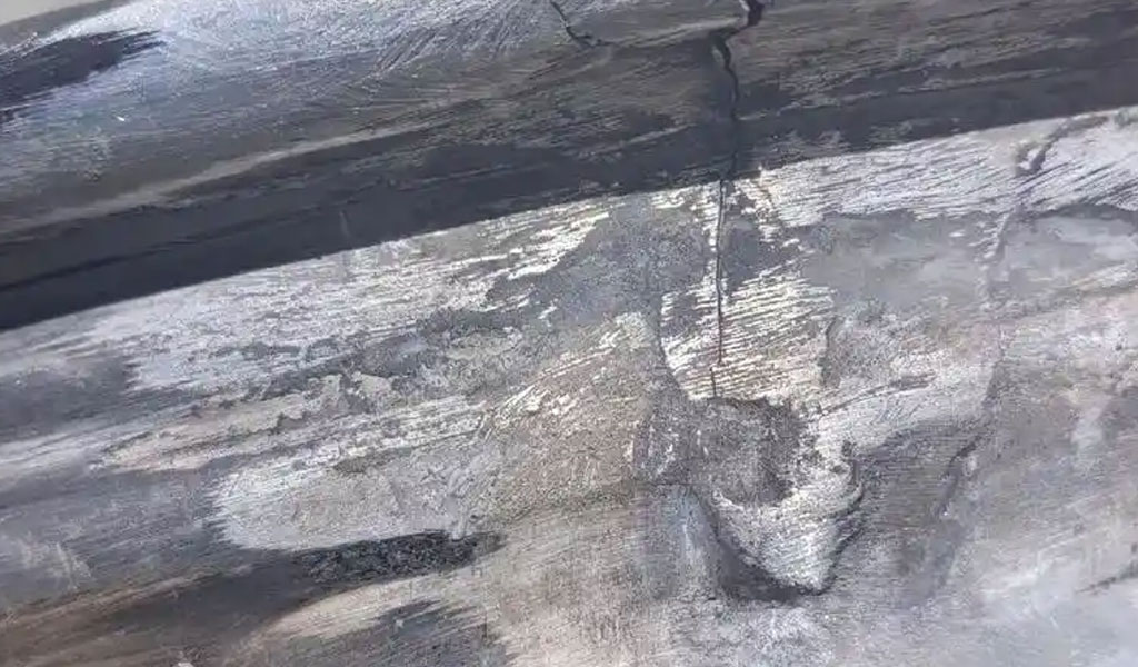
Cracks in metals represent critical defects that can compromise the structural integrity, mechanical performance, and longevity of metallic components across various industries, including aerospace, automotive, construction, and manufacturing. These imperfections, ranging from microscopic fissures to macroscopic fractures, arise due to a complex interplay of material properties, manufacturing processes, environmental conditions, and applied stresses. Understanding the types, causes, mechanisms, and characteristics of cracks in metals is essential for engineers, metallurgists, and material scientists to design robust components, implement effective inspection techniques, and develop strategies for crack mitigation and prevention. This article provides a comprehensive exploration of the various types of cracks in metals, their formation mechanisms, influencing factors, and practical implications, supported by detailed comparative tables.
Introduction to Cracks in Metals
A crack in a metal is defined as a planar or near-planar discontinuity within the material's microstructure, resulting in a partial or complete separation of the material. Cracks can initiate at the surface or within the bulk of the metal and propagate under mechanical, thermal, or environmental influences. They are often categorized based on their origin, morphology, propagation behavior, and the underlying mechanisms driving their formation. The study of cracks is rooted in fracture mechanics, a field that quantifies crack behavior using parameters such as stress intensity factor (K), crack tip opening displacement (CTOD), and J-integral.
Cracks in metals are a significant concern because they can lead to catastrophic failures, as seen in historical incidents like the Liberty ship failures during World War II or the Aloha Airlines Flight 243 accident in 1988, where fatigue cracking played a pivotal role. By classifying cracks systematically, researchers and engineers can better predict their behavior, assess their impact on material performance, and develop strategies to enhance material durability.
This article is structured to provide a detailed examination of the primary types of cracks in metals, including fatigue cracks, stress corrosion cracks, hydrogen-induced cracks, creep cracks, and others. Each section discusses the mechanisms, influencing factors, detection methods, and mitigation strategies, with comparative tables to highlight key differences.
Fatigue Cracks
Definition and Characteristics
Fatigue cracks are among the most common types of cracks in metals subjected to cyclic loading. These cracks initiate and propagate due to repeated stress applications, even when the stress levels are below the material’s yield strength. Fatigue cracking is a time-dependent process characterized by three stages: initiation, propagation, and final fracture.
-
Initiation: Fatigue cracks typically initiate at stress concentration points, such as surface imperfections, inclusions, notches, or microstructural heterogeneities. For instance, a scratch on a metal surface or a sharp corner in a component can act as a stress raiser, promoting crack nucleation.
-
Propagation: Once initiated, the crack grows incrementally with each loading cycle. The crack front advances through the material, often leaving characteristic striations visible under a microscope, known as fatigue striations.
-
Final Fracture: When the crack reaches a critical size, the remaining cross-sectional area can no longer sustain the applied load, leading to sudden failure.
Mechanisms of Fatigue Crack Formation
The formation of fatigue cracks is governed by the accumulation of plastic deformation at the crack tip. Under cyclic loading, localized plastic strain develops, leading to the formation of persistent slip bands (PSBs) within the metal’s crystal structure. These bands create microscopic extrusions and intrusions on the surface, which serve as crack initiation sites. The crack then propagates through a process of incremental growth, driven by the stress intensity factor at the crack tip, described by Paris’ Law:
[ \frac{da}{dN} = C (\Delta K)^m ]
where ( \frac{da}{dN} ) is the crack growth rate per cycle, ( \Delta K ) is the stress intensity factor range, and ( C ) and ( m ) are material constants.
Influencing Factors
Several factors influence fatigue crack initiation and propagation:
-
Stress Amplitude: Higher stress amplitudes accelerate crack growth.
-
Mean Stress: A positive mean stress (tensile) increases crack growth rates, while compressive stresses may retard growth.
-
Material Properties: Ductile metals, such as aluminum alloys, exhibit slower crack growth compared to brittle metals like high-strength steels.
-
Surface Finish: Polished surfaces reduce the likelihood of crack initiation compared to rough or scratched surfaces.
-
Environmental Conditions: Corrosive environments, such as saltwater exposure, can exacerbate fatigue cracking through corrosion fatigue.
Detection and Mitigation
Fatigue cracks are detected using non-destructive testing (NDT) methods, such as ultrasonic testing, magnetic particle inspection, and dye penetrant testing. Mitigation strategies include:
-
Design Improvements: Reducing stress concentrations through smooth geometries and avoiding sharp corners.
-
Material Selection: Using high-fatigue-strength alloys, such as titanium or nickel-based superalloys.
-
Surface Treatments: Applying shot peening or laser shock peening to induce compressive residual stresses, which inhibit crack initiation.
-
Load Management: Reducing cyclic loading amplitudes or frequencies in critical components.
Stress Corrosion Cracking (SCC)
Definition and Characteristics
Stress corrosion cracking (SCC) is a degradation process that occurs in susceptible metals exposed to a corrosive environment under sustained tensile stress. Unlike fatigue cracks, which require cyclic loading, SCC can occur under static loads. SCC is characterized by the formation of brittle cracks that propagate through the material, often along grain boundaries (intergranular SCC) or through the grains (transgranular SCC).
Mechanisms of SCC
SCC results from the synergistic interaction of three factors:
-
Tensile Stress: This can be applied externally (e.g., mechanical loading) or arise from residual stresses (e.g., from welding or cold working).
-
Corrosive Environment: Specific environments, such as chloride solutions for stainless steels or ammonia for brass, promote SCC.
-
Susceptible Material: Certain alloys, such as austenitic stainless steels or high-strength aluminum alloys, are particularly prone to SCC.
The crack propagation mechanism in SCC involves anodic dissolution at the crack tip, where the metal corrodes preferentially, coupled with mechanical crack opening due to stress. For example, in chloride-induced SCC of stainless steel, the protective oxide layer breaks down, exposing the metal to localized corrosion, which accelerates crack growth.
Influencing Factors
-
Alloy Composition: High-strength alloys with specific microstructures (e.g., martensitic steels) are more susceptible to SCC.
-
Environmental Conditions: Temperature, pH, and the presence of specific ions (e.g., chlorides, sulfides) significantly affect SCC susceptibility.
-
Stress Levels: Higher tensile stresses accelerate crack growth, with a threshold stress intensity factor (( K_{ISCC} )) below which SCC does not occur.
-
Microstructure: Grain size, phase distribution, and the presence of second-phase particles influence SCC behavior.
Detection and Mitigation
SCC is detected using NDT techniques like eddy current testing or acoustic emission monitoring. Mitigation strategies include:
-
Material Selection: Choosing alloys with low SCC susceptibility, such as duplex stainless steels instead of austenitic grades in chloride environments.
-
Environmental Control: Reducing exposure to corrosive media through coatings, inhibitors, or environmental modification (e.g., lowering temperature).
-
Stress Reduction: Annealing to relieve residual stresses or designing components to minimize tensile stresses.
-
Cathodic Protection: Applying an external electric potential to prevent anodic dissolution.
Hydrogen-Induced Cracking (HIC)
Definition and Characteristics
Hydrogen-induced cracking (HIC), also known as hydrogen embrittlement cracking, occurs when atomic hydrogen diffuses into a metal, reducing its ductility and promoting brittle fracture. HIC is particularly prevalent in high-strength steels and titanium alloys exposed to hydrogen-rich environments, such as during welding, electroplating, or service in hydrogen-containing atmospheres.
Mechanisms of HIC
Hydrogen atoms, due to their small size, diffuse readily into the metal lattice, particularly at lattice defects, grain boundaries, or inclusions. The presence of hydrogen leads to several mechanisms:
-
Hydrogen-Enhanced Decohesion (HEDE): Hydrogen reduces the cohesive strength of atomic bonds, promoting cleavage-like fracture.
-
Hydrogen-Enhanced Localized Plasticity (HELP): Hydrogen increases localized plastic deformation, leading to microvoid formation and crack initiation.
-
Pressure Buildup: Hydrogen atoms recombine to form hydrogen gas (H₂) within voids or inclusions, creating internal pressure that drives crack growth.
HIC typically manifests as internal cracks parallel to the surface (e.g., in pipelines) or as surface-breaking cracks in components under tensile stress.
Influencing Factors
-
Hydrogen Source: Common sources include welding (moisture in electrodes), corrosion reactions (e.g., in sour gas environments), or cathodic overprotection.
-
Material Susceptibility: High-strength steels with hardness above 350 HV are particularly vulnerable.
-
Stress State: Tensile stresses, whether applied or residual, exacerbate HIC.
-
Microstructure: Martensitic or bainitic microstructures are more susceptible than ferritic or pearlitic ones.
Detection and Mitigation
HIC is detected using ultrasonic testing or magnetic flux leakage testing, particularly in pipelines. Mitigation strategies include:
-
Material Selection: Using low-hydrogen-susceptible alloys, such as low-carbon steels or alloys with specific inhibitors.
-
Process Control: Employing low-hydrogen welding techniques (e.g., using low-hydrogen electrodes) or post-weld heat treatment to diffuse hydrogen out.
-
Environmental Control: Avoiding hydrogen-rich environments or using inhibitors to reduce hydrogen uptake.
-
Coating and Plating: Applying diffusion barriers to prevent hydrogen ingress.
Creep Cracks
Definition and Characteristics
Creep cracks form in metals subjected to sustained high temperatures and stresses, typically above 0.4 times the material’s melting point (in Kelvin). Creep is a time-dependent deformation process, and creep cracks develop as a result of accumulated damage under prolonged loading. These cracks are common in high-temperature applications, such as turbine blades, boiler tubes, and nuclear reactor components.
Mechanisms of Creep Crack Formation
Creep cracking occurs through three stages of creep deformation:
-
Primary Creep: Initial deformation with a decreasing strain rate as the material work-hardens.
-
Secondary Creep: Steady-state deformation with a constant strain rate, where creep cracks may initiate at grain boundaries or voids.
-
Tertiary Creep: Accelerated deformation leading to crack propagation and eventual failure.
Creep cracks often initiate at grain boundaries due to mechanisms like grain boundary sliding, vacancy diffusion (Nabarro-Herring or Coble creep), or void coalescence. The cracks may be intergranular or transgranular, depending on the material and conditions.
Influencing Factors
-
Temperature: Higher temperatures accelerate creep and crack formation.
-
Stress Levels: Higher stresses reduce the time to crack initiation and increase crack growth rates.
-
Material Properties: Creep-resistant alloys, such as nickel-based superalloys, exhibit slower crack growth.
-
Microstructure: Fine-grained materials may resist creep better at lower temperatures, while coarse-grained materials perform better at higher temperatures.
-
Environment: Oxidative or corrosive environments can accelerate creep crack growth through surface degradation.
Detection and Mitigation
Creep cracks are detected using high-temperature NDT methods, such as infrared thermography or acoustic emission. Mitigation strategies include:
-
Material Selection: Using creep-resistant alloys, such as Inconel or Haynes alloys, for high-temperature applications.
-
Design Optimization: Reducing stress concentrations and optimizing component geometry to minimize creep deformation.
-
Temperature Control: Operating components below critical temperature thresholds.
-
Protective Coatings: Applying thermal barrier coatings to reduce surface degradation.
Other Types of Cracks
Thermal Cracks
Thermal cracks, also known as heat checking or thermal fatigue cracks, result from cyclic thermal stresses induced by rapid temperature changes. These cracks are common in components like molds, dies, or turbine blades exposed to thermal cycling. The mechanism involves differential thermal expansion and contraction, which generate tensile and compressive stresses. Thermal cracks are typically surface-initiated and propagate perpendicular to the surface.
Quench Cracks
Quench cracks occur during rapid cooling (quenching) of metals, particularly during heat treatment processes like hardening. The rapid cooling induces high thermal gradients and transformation stresses (e.g., during martensitic transformation in steels), leading to crack formation. Quench cracks are typically brittle and transgranular, with a characteristic “starburst” appearance radiating from a central point.
Weld Imperfection Cracks
Cracks associated with welding, such as hot cracks and cold cracks, arise due to thermal and mechanical stresses during the welding process. Hot cracks form during weld solidification due to shrinkage stresses and low-melting-point phases, while cold cracks (e.g., hydrogen-induced weld cracks) form after cooling due to residual stresses and hydrogen embrittlement. These cracks are often intergranular and located in the weld metal or heat-affected zone (HAZ).
Corrosion Fatigue Cracks
Corrosion fatigue cracks occur when cyclic loading and a corrosive environment act synergistically to accelerate crack growth. These cracks combine the characteristics of fatigue and SCC, with corrosion at the crack tip reducing the fatigue life of the material. They are common in marine structures, pipelines, and aircraft components exposed to corrosive media.
Comparative Analysis of Crack Types
To facilitate a clear understanding of the differences between crack types, the following tables provide a detailed comparison based on key parameters.
Table 1: Characteristics of Major Crack Types
|
Crack Type |
Initiation Mechanism |
Propagation Mechanism |
Typical Location |
Common Materials Affected |
|---|---|---|---|---|
|
Fatigue Crack |
Cyclic loading at stress concentrations |
Incremental growth via Paris’ Law |
Surface or near-surface |
Aluminum, steel, titanium alloys |
|
Stress Corrosion Cracking |
Tensile stress + corrosive environment |
Anodic dissolution + mechanical opening |
Surface or intergranular |
Austenitic stainless steel, aluminum alloys |
|
Hydrogen-Induced Cracking |
Hydrogen diffusion into lattice |
Decohesion, localized plasticity, or pressure buildup |
Internal or surface-breaking |
High-strength steels, titanium alloys |
|
Creep Crack |
Sustained stress at high temperature |
Grain boundary sliding, void coalescence |
Grain boundaries or transgranular |
Nickel-based superalloys, creep-resistant steels |
|
Thermal Crack |
Thermal cycling stresses |
Differential expansion/contraction |
Surface |
Tool steels, die materials |
|
Quench Crack |
Rapid cooling stresses |
Brittle fracture during transformation |
Surface or bulk |
High-carbon steels, alloy steels |
|
Weld Imperfection Crack |
Weld shrinkage or hydrogen embrittlement |
Solidification or post-weld stresses |
Weld metal or HAZ |
Weldable steels, aluminum alloys |
|
Corrosion Fatigue Crack |
Cyclic loading + corrosive environment |
Fatigue + corrosion-enhanced growth |
Surface |
Marine-grade steels, aluminum alloys |
Table 2: Influencing Factors and Mitigation Strategies
|
Crack Type |
Key Influencing Factors |
Detection Methods |
Mitigation Strategies |
|---|---|---|---|
|
Fatigue Crack |
Stress amplitude, surface finish, environment |
Ultrasonic, magnetic particle, dye penetrant |
Surface treatments, design optimization |
|
Stress Corrosion Cracking |
Alloy composition, environment, stress level |
Eddy current, acoustic emission |
Material selection, environmental control |
|
Hydrogen-Induced Cracking |
Hydrogen source, material hardness, stress |
Ultrasonic, magnetic flux leakage |
Low-hydrogen welding, coatings |
|
Creep Crack |
Temperature, stress, microstructure |
Infrared thermography, acoustic emission |
Creep-resistant alloys, temperature control |
|
Thermal Crack |
Thermal gradient, cycling frequency |
Visual inspection, dye penetrant |
Thermal management, material selection |
|
Quench Crack |
Cooling rate, material composition |
Visual inspection, magnetic particle |
Controlled quenching, material selection |
|
Weld Imperfection Crack |
Weld parameters, hydrogen content |
Radiography, ultrasonic testing |
Proper welding techniques, post-weld treatment |
|
Corrosion Fatigue Crack |
Cyclic loading, corrosive environment |
Ultrasonic, eddy current |
Corrosion-resistant coatings, load reduction |
Practical Implications and Case Studies
Aerospace Industry
In aerospace, fatigue cracks are a primary concern due to the cyclic loading experienced by aircraft components, such as wings and landing gear. The Aloha Airlines Flight 243 incident (1988) highlighted the dangers of fatigue cracking, where multiple-site damage (MSD) led to catastrophic fuselage failure. Modern aircraft employ advanced NDT techniques and fatigue-resistant materials like titanium alloys to mitigate such risks.
Oil and Gas Industry
Hydrogen-induced cracking is a significant issue in pipelines transporting sour gas (containing H₂S). HIC can lead to pipeline leaks or ruptures, causing environmental and economic damage. The use of HIC-resistant steels and cathodic protection systems has significantly reduced the incidence of HIC in modern pipelines.
Power Generation
Creep cracks are prevalent in power plant components, such as boiler tubes and turbine blades, operating at high temperatures. The development of creep-resistant superalloys and thermal barrier coatings has extended the service life of these components, improving plant efficiency and safety.
Marine Applications
Corrosion fatigue and SCC are critical in marine environments, where components like ship hulls and offshore platforms are exposed to seawater. Duplex stainless steels and cathodic protection systems are commonly used to combat these issues, reducing maintenance costs and extending service life.
Advanced Research and Future Directions
Recent advancements in materials science and fracture mechanics have led to improved understanding and management of cracks in metals. Key research areas include:
-
High-Resolution Imaging: Techniques like X-ray computed tomography (CT) and electron backscatter diffraction (EBSD) allow detailed characterization of crack morphology and propagation.
-
Computational Modeling: Finite element analysis (FEA) and molecular dynamics simulations provide insights into crack initiation and growth at the atomic and macroscopic levels.
-
Smart Materials: Development of self-healing metals and alloys with embedded sensors to detect and repair cracks autonomously.
-
Machine Learning: Predictive models using machine learning to forecast crack initiation and propagation based on material and environmental data.
Future research aims to develop materials with enhanced resistance to cracking, improved NDT techniques for real-time monitoring, and sustainable manufacturing processes to minimize crack-inducing defects.
Conclusion
Cracks in metals are a multifaceted challenge that requires a deep understanding of material science, mechanics, and environmental interactions. By categorizing cracks into types such as fatigue, stress corrosion, hydrogen-induced, and creep cracks, engineers can tailor detection and mitigation strategies to specific applications. The comparative tables provided in this article highlight the distinct characteristics, mechanisms, and management approaches for each crack type, serving as a valuable resource for researchers and practitioners. As industries continue to push the boundaries of material performance, ongoing research and innovation will play a critical role in minimizing the impact of cracks and ensuring the reliability of metallic components.
Reprint Statement: If there are no special instructions, all articles on this site are original. Please indicate the source for reprinting:https://www.cncmachiningptj.com/,thanks!
 PTJ® provides a full range of Custom Precision cnc machining china services.ISO 9001:2015 &AS-9100 certified. 3, 4 and 5-axis rapid precision CNC machining services including milling, turning to customer specifications,Capable of metal & plastic machined parts with +/-0.005 mm tolerance.Secondary services include CNC and conventional grinding, drilling,die casting,sheet metal and stamping.Providing prototypes, full production runs, technical support and full inspection.Serves the automotive, aerospace, mold&fixture,led lighting,medical,bicycle, and consumer electronics industries. On-time delivery.Tell us a little about your project's budget and expected delivery time. We will strategize with you to provide the most cost-effective services to help you reach your target,Welcome to Contact us ( [email protected] ) directly for your new project.
- 5 Axis Machining
- Cnc Milling
- Cnc Turning
- Machining Industries
- Machining Process
- Surface Treatment
- Metal Machining
- Plastic Machining
- Powder Metallurgy Mold
- Die Casting
- Parts Gallery
- Auto Metal Parts
- Machinery Parts
- LED Heatsink
- Building Parts
- Mobile Parts
- Medical Parts
- Electronic Parts
- Tailored Machining
- Bicycle Parts
- Aluminum Machining
- Titanium Machining
- Stainless Steel Machining
- Copper Machining
- Brass Machining
- Super Alloy Machining
- Peek Machining
- UHMW Machining
- Unilate Machining
- PA6 Machining
- PPS Machining
- Teflon Machining
- Inconel Machining
- Tool Steel Machining
- More Material

