Fiber Tearing Mechanism in CNC Machining of Aerospace Composite Materials
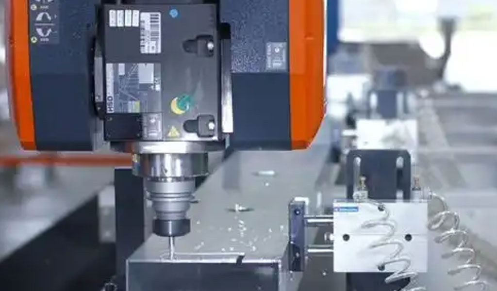
Composite materials, particularly fiber-reinforced plastics (FRPs) such as carbon fiber-reinforced polymers (CFRPs) and glass fiber-reinforced polymers (GFRPs), have become integral to the aerospace industry due to their exceptional strength-to-weight ratio, corrosion resistance, and design flexibility. These materials are widely used in critical components like aircraft fuselages, wings, and engine parts, where lightweight structures are paramount for fuel efficiency and performance. However, the machining of these composites, particularly through computer numerical control (CNC) processes, presents significant challenges due to their anisotropic and heterogeneous microstructures. One of the most critical issues encountered during CNC machining of aerospace composites is fiber tearing, a surface integrity defect that compromises the structural performance and longevity of machined parts.
Fiber tearing refers to the mechanical disruption of reinforcing fibers within the composite matrix during machining, resulting in frayed, pulled-out, or fractured fibers on the machined surface. This phenomenon is distinct from other machining-induced defects like delamination or matrix cracking, as it specifically involves the physical tearing of fibers due to improper cutting conditions, tool geometry, or material properties. Fiber tearing not only degrades the aesthetic quality of the machined surface but also reduces the mechanical strength and fatigue resistance of the component, which is particularly critical in aerospace applications where safety and reliability are non-negotiable.
This article provides a comprehensive exploration of the fiber tearing mechanism in CNC machining of aerospace composite materials. It covers the fundamental properties of composites, the mechanics of fiber tearing, the influence of machining parameters, tool design, and recent advancements in mitigating this defect. The discussion is grounded in scientific principles and supported by detailed tables comparing key parameters and outcomes. The article aims to serve as a definitive resource for researchers, engineers, and manufacturers seeking to understand and address fiber tearing in aerospace composite machining.
Composite Materials in Aerospace: Composition and Properties
Overview of Fiber-Reinforced Composites
Fiber-reinforced composites consist of a matrix material, typically a polymer (e.g., epoxy, polyester), reinforced with high-strength fibers such as carbon, glass, or aramid. The matrix binds the fibers, providing shape and protecting them from environmental factors, while the fibers contribute mechanical strength and stiffness. In aerospace, CFRPs dominate due to their superior tensile strength and modulus, with carbon fibers embedded in an epoxy matrix being the most common configuration. GFRPs and aramid fiber-reinforced polymers (e.g., Kevlar) are also used in specific applications, such as radomes or ballistic components, due to their unique properties like electrical non-conductivity or impact resistance.
The microstructure of FRPs is inherently anisotropic, meaning their mechanical properties vary with direction. Fibers can be arranged unidirectionally, woven, or in multi-layered laminates, each configuration influencing the material’s response to machining forces. The interface between the fiber and matrix is critical, as it governs load transfer and the composite’s overall integrity. Weak interfacial bonding can exacerbate fiber tearing, as fibers are more likely to be pulled out rather than cleanly cut.
Mechanical and Physical Properties Relevant to Machining
The machining behavior of composites is governed by their mechanical and physical properties, which differ significantly from metals. Key properties include:
-
High Hardness and Abrasiveness: Carbon and glass fibers are extremely hard and abrasive, causing rapid tool wear during machining. For example, carbon fibers have a Vickers hardness of approximately 600–800 HV, compared to 150–200 HV for aluminum alloys.
-
Anisotropy: The directional dependence of mechanical properties means that cutting forces vary depending on the fiber orientation relative to the cutting tool. Fibers oriented at 90° to the cutting direction are particularly prone to tearing.
-
Low Thermal Conductivity: Composites have poor heat dissipation, leading to localized heat buildup during machining, which can soften the matrix and increase the risk of fiber tearing.
-
Brittle Behavior: Unlike metals, which deform plastically, composites exhibit brittle fracture, with fibers fracturing rather than shearing smoothly. This contributes to the jagged, torn appearance of machined surfaces.
These properties make CNC machining of composites a complex process, requiring specialized tools and parameters to minimize defects like fiber tearing.
Aerospace Applications and Machining Requirements
In aerospace, composites are used in primary structures (e.g., Airbus A350’s 50% composite airframe by weight) and secondary components (e.g., interior panels, fairings). Machining is often required to achieve precise geometries, drill holes for fasteners, or trim excess material after molding. CNC machining is preferred for its precision and ability to handle complex shapes, but the process must meet stringent aerospace standards, such as AS9100, which demand minimal surface defects and tight tolerances (e.g., ±0.05 mm for critical components).
Fiber tearing is particularly problematic in aerospace because it can initiate crack propagation under cyclic loading, reducing fatigue life. For instance, a torn fiber on a wing skin could serve as a stress concentration point, compromising the component’s ability to withstand aerodynamic forces. Thus, understanding and mitigating fiber tearing is essential for ensuring the reliability of aerospace composites.
Mechanics of Fiber Tearing
Definition and Characteristics
Fiber tearing occurs when the cutting tool fails to cleanly sever the reinforcing fibers, instead causing them to fray, pull out, or fracture irregularly. This results in a rough surface with exposed, damaged fibers, often accompanied by matrix smearing or cracking. The defect is most pronounced in CFRPs due to the high strength and brittleness of carbon fibers, but it can also occur in GFRPs and aramid composites, albeit with different manifestations (e.g., aramid fibers tend to form fuzzy surfaces due to their toughness).
Microscopically, fiber tearing is characterized by:
-
Fiber Pull-Out: Fibers are extracted from the matrix due to insufficient interfacial bonding or excessive axial cutting forces.
-
Fiber Fracture: Fibers break irregularly, often at angles misaligned with the intended cut, due to bending or shearing stresses.
-
Matrix Damage: The surrounding matrix may crack or smear, further exposing fibers and exacerbating surface roughness.
These characteristics can be observed using scanning electron microscopy (SEM), which reveals the jagged, uneven nature of torn fibers compared to cleanly cut surfaces.
Mechanisms of Fiber Tearing
The fiber tearing mechanism is driven by the interaction between the cutting tool, the composite’s microstructure, and the machining parameters. Several key mechanisms contribute to this defect:
-
Shear-Induced Fiber Failure: When the cutting tool engages fibers at an angle (e.g., 45° or 90° to the fiber orientation), shear stresses dominate, causing fibers to bend and fracture rather than cut cleanly. This is particularly common in orthogonal cutting, where the tool’s rake angle is insufficient to produce a sharp cutting action.
-
Axial Force Dominance: High axial forces, perpendicular to the machined surface, can pull fibers out of the matrix rather than severing them. This is exacerbated by worn tools, which increase frictional forces and reduce cutting efficiency.
-
Tool Edge Radius Effects: A dull or large-radius tool edge crushes fibers instead of cutting them, leading to tearing and surface damage. Sharp tools with low edge radii (e.g., <10 μm) are critical for minimizing this effect.
-
Fiber Orientation Effects: Fibers oriented perpendicular to the cutting direction (90°) experience maximum resistance to cutting, increasing the likelihood of tearing. Conversely, parallel fibers (0°) are easier to cut but may still tear if the tool is misaligned or the feed rate is too high.
-
Matrix-Fiber Debonding: Weak interfacial bonding allows fibers to detach from the matrix under cutting forces, resulting in pull-out and tearing. This is influenced by the composite’s manufacturing quality, such as resin curing conditions or fiber surface treatments.
These mechanisms are interdependent, with tool wear, cutting speed, and feed rate amplifying their effects. For example, a high feed rate increases axial forces, which, combined with a worn tool, can cause severe fiber tearing.
Mathematical Modeling of Fiber Tearing
To quantify the fiber tearing mechanism, researchers have developed models based on cutting mechanics and fracture mechanics. A simplified model for the cutting force ( F_c ) in composite machining can be expressed as:
[ F_c = K_c \cdot t \cdot w ]
where:
-
( K_c ): Specific cutting force (N/mm²), dependent on material properties and fiber orientation.
-
( t ): Depth of cut (mm).
-
( w ): Width of cut (mm).
For fiber tearing, the axial force component ( F_a ) is critical, as it drives fiber pull-out. This can be modeled as:
[ F_a = \mu \cdot F_c + F_f ]
where:
-
( \mu ): Friction coefficient between the tool and composite.
-
( F_f ): Fiber fracture force, proportional to the fiber’s tensile strength and cross-sectional area.
The propensity for fiber tearing increases when ( F_a ) exceeds the interfacial shear strength ( \tau_i ) of the fiber-matrix bond, given by:
[ \tau_i = \frac{F_a}{A_f} ]
where ( A_f ) is the fiber’s surface area in contact with the matrix. If ( \tau_i ) is low (e.g., due to poor bonding), fibers are more likely to tear or pull out.
Finite element analysis (FEA) is also used to simulate fiber tearing, incorporating anisotropic material properties and tool-workpiece interactions. These models predict stress distributions and failure modes, aiding in the optimization of machining parameters.
Influence of Machining Parameters on Fiber Tearing
Cutting Speed
Cutting speed, measured in surface feet per minute (sfm) or meters per minute (m/min), significantly affects fiber tearing. High cutting speeds (e.g., 400–500 sfm) generate excessive heat due to the low thermal conductivity of composites, softening the matrix and increasing fiber mobility, which promotes tearing. Conversely, low speeds (e.g., <200 sfm) may cause rubbing rather than cutting, leading to chatter and fiber damage.
Optimal cutting speeds vary by material. For CFRPs, speeds of 300–400 sfm are recommended, balancing heat generation and cutting efficiency. GFRPs can tolerate slightly higher speeds (400–500 sfm) due to the lower abrasiveness of glass fibers. Table 1 summarizes recommended cutting speeds for common aerospace composites.
Table 1: Recommended Cutting Speeds for CNC Machining of Aerospace Composites
|
Material |
Cutting Speed (sfm) |
Cutting Speed (m/min) |
Notes |
|---|---|---|---|
|
CFRP (Epoxy Matrix) |
300–400 |
91–122 |
Risk of heat buildup at >400 sfm |
|
GFRP (Polyester Matrix) |
400–500 |
122–152 |
Less abrasive than CFRP |
|
Aramid FRP (Epoxy Matrix) |
200–300 |
61–91 |
Prone to fuzzing at high speeds |
|
Hybrid (CFRP/Aluminum) |
250–350 |
76–107 |
Adjust for metal layer properties |
Feed Rate
Feed rate, or the rate at which the tool advances per revolution (in/rev or mm/rev), influences chip load and cutting forces. High feed rates (e.g., >0.003 in/rev) increase axial forces, promoting fiber pull-out and tearing. Low feed rates (e.g., <0.001 in/rev) reduce forces but may cause rubbing, leading to surface roughness and fiber damage.
For CFRPs, a feed rate of 0.002–0.003 in/rev (0.05–0.075 mm/rev) is optimal, providing a balance between productivity and surface quality. Table 2 compares feed rate effects on fiber tearing.
Table 2: Effect of Feed Rate on Fiber Tearing in CFRP Machining
|
Feed Rate (in/rev) |
Feed Rate (mm/rev) |
Fiber Tearing Severity |
Surface Roughness (Ra, μm) |
Tool Wear Rate |
|---|---|---|---|---|
|
0.001 |
0.025 |
Low |
1.2–1.5 |
Moderate |
|
0.002 |
0.05 |
Minimal |
0.8–1.0 |
Low |
|
0.003 |
0.075 |
Moderate |
1.0–1.3 |
Moderate |
|
0.005 |
0.125 |
High |
1.5–2.0 |
High |
Depth of Cut
Depth of cut (DOC) affects the volume of material removed per pass and the magnitude of cutting forces. Deep cuts (e.g., >0.1 in or 2.5 mm) increase axial forces, exacerbating fiber tearing, while shallow cuts (e.g., <0.02 in or 0.5 mm) reduce forces but may require multiple passes, increasing machining time.
For aerospace composites, a DOC of 0.02–0.05 in (0.5–1.25 mm) is typically recommended to minimize fiber tearing while maintaining efficiency. Table 3 illustrates the impact of DOC on machining outcomes.
Table 3: Impact of Depth of Cut on Fiber Tearing in CFRP Machining
|
Depth of Cut (in) |
Depth of Cut (mm) |
Fiber Tearing Severity |
Cutting Force (N) |
Machining Time (min) |
|---|---|---|---|---|
|
0.01 |
0.25 |
Minimal |
50–100 |
10–15 |
|
0.02 |
0.5 |
Low |
100–150 |
8–12 |
|
0.05 |
1.25 |
Moderate |
150–200 |
6–10 |
|
0.1 |
2.5 |
High |
200–300 |
4–8 |
Fiber Orientation
Fiber orientation relative to the cutting direction is a critical factor in fiber tearing. Fibers at 90° to the tool path experience maximum shear stress, leading to severe tearing, while 0° fibers are cut more cleanly. Intermediate angles (e.g., 45°) produce moderate tearing, depending on tool geometry and parameters.
Table 4 summarizes the effect of fiber orientation on fiber tearing severity.
Table 4: Effect of Fiber Orientation on Fiber Tearing in CFRP Machining
|
Fiber Orientation (°) |
Fiber Tearing Severity |
Surface Quality |
Recommended Tool Type |
|---|---|---|---|
|
0 |
Minimal |
Excellent |
Carbide, PCD |
|
45 |
Moderate |
Good |
PCD, Diamond-Coated |
|
90 |
High |
Poor |
PCD, Compression Helix Cutter |
|
135 |
Severe |
Very Poor |
PCD, Specialized Geometry |
Tool Design and Material Selection
Tool Materials
The abrasive nature of composite fibers necessitates the use of high-hardness tool materials to resist wear and maintain sharpness. Common tool materials include:
-
Cemented Carbide: Offers good toughness and moderate wear resistance but wears rapidly when machining CFRPs. Suitable for low-volume production or less abrasive composites like GFRPs.
-
Polycrystalline Diamond (PCD): Provides exceptional hardness (8000–12000 HV) and wear resistance, making it ideal for CFRPs. PCD tools can be resharpened up to 10 times, reducing costs.
-
Diamond-Coated Carbide: Combines carbide’s toughness with a diamond coating for enhanced wear resistance. Less expensive than PCD but with shorter tool life.
-
Cubic Boron Nitride (CBN): Used for hybrid composites with metal layers (e.g., CFRP/titanium stacks) due to its high thermal stability.
Table 5 compares tool materials for composite machining.
Table 5: Comparison of Tool Materials for CNC Machining of Aerospace Composites
|
Tool Material |
Hardness (HV) |
Wear Resistance |
Tool Life (m) |
Cost ($/tool) |
Applications |
|---|---|---|---|---|---|
|
Cemented Carbide |
1500–2000 |
Moderate |
10–50 |
50–100 |
GFRP, Low-Volume CFRP |
|
PCD |
8000–12000 |
Excellent |
100–500 |
200–500 |
CFRP, High-Volume Production |
|
Diamond-Coated Carbide |
3000–5000 |
High |
50–200 |
100–200 |
CFRP, Medium-Volume Production |
|
CBN |
4000–6000 |
High |
50–150 |
150–300 |
Hybrid Composites, Metal Stacks |
Tool Geometry
Tool geometry plays a pivotal role in minimizing fiber tearing. Key geometric features include:
-
Rake Angle: A high positive rake angle (e.g., 10°–20°) promotes sharp cutting and reduces axial forces, minimizing fiber tearing. Negative rake angles increase crushing and tearing.
-
Clearance Angle: A clearance angle of 5°–10° reduces friction between the tool flank and workpiece, preventing rubbing-induced tearing.
-
Helix Angle: Compression helix cutters, with a combination of up- and down-cut flutes, reduce delamination and fiber tearing by applying balanced forces to the composite layers.
-
Edge Radius: A sharp edge (radius <10 μm) is essential for clean fiber cutting. Worn tools with larger radii crush fibers, increasing tearing.
Specialized geometries, such as veined PCD tools, allow for complex cutting profiles tailored to CFRPs, reducing tearing in challenging orientations (e.g., 90° fibers).
Tool Wear and Its Impact on Fiber Tearing
Tool wear accelerates fiber tearing by increasing cutting forces and dulling the cutting edge. Abrasive wear is the dominant mechanism in composite machining, with carbon fibers eroding the tool’s edge, leading to a larger edge radius and higher friction. Flank wear and edge rounding are common, reducing the tool’s ability to cut fibers cleanly.
Regular tool inspection and replacement are critical in aerospace machining to prevent fiber tearing. Advanced tool monitoring systems, using acoustic emission or force sensors, can detect wear in real-time, ensuring consistent surface quality.
Strategies to Mitigate Fiber Tearing
Optimized Machining Parameters
Selecting optimal cutting speed, feed rate, and depth of cut is the first step in mitigating fiber tearing. As discussed, moderate speeds (300–400 sfm for CFRPs), feed rates (0.002–0.003 in/rev), and shallow cuts (0.02–0.05 in) minimize axial forces and heat buildup. Parameter optimization often requires experimental trials or simulation using FEA to balance productivity and surface quality.
Advanced Tooling Solutions
Using PCD or diamond-coated tools with specialized geometries, such as compression helix cutters, significantly reduces fiber tearing. Veined PCD tools, which incorporate diamond veins within a carbide substrate, offer tailored cutting profiles for CFRPs, minimizing tearing in high-risk orientations.
Coolant and Dust Management
Machining composites generates significant dust, which can exacerbate tool wear and fiber tearing by clogging the cutting zone. Effective dust extraction systems, such as high-efficiency particulate air (HEPA) filters, are essential. Coolants, when permitted, can reduce heat buildup and improve surface quality. However, water-based coolants are often avoided in aerospace due to their potential to degrade CFRPs. Dry machining with mist cooling or cryogenic cooling (using liquid nitrogen) is increasingly used to control heat and dust without compromising material integrity.
Vibration-Assisted Machining
Vibration-assisted machining (VAM), such as ultrasonic-assisted drilling, introduces high-frequency vibrations to the cutting tool, reducing cutting forces and improving chip evacuation. This technique has been shown to decrease fiber tearing by promoting cleaner fiber fracture. For example, a study by the Fraunhofer Joint Laboratory (2016) demonstrated a 30% reduction in fiber pull-out during vibration-assisted drilling of CFRPs compared to conventional drilling.
Workholding and Fixturing
Proper workholding is critical to prevent vibrations, which can amplify fiber tearing. Rigid fixtures, such as vacuum chucks or backing plates, stabilize the workpiece, especially for thin composite sheets prone to flexing. Hydraulic chucks for tool holders also minimize run-out, ensuring precise tool engagement and reducing tearing.
Recent Advancements in Composite Machining
Hybrid Machining Technologies
Hybrid machining, combining multiple energy sources (e.g., laser-assisted machining, ultrasonic-assisted machining), is an emerging solution for reducing fiber tearing. Laser-assisted machining preheats the composite surface, softening the matrix and reducing cutting forces, while ultrasonic vibrations enhance fiber fracture precision. These technologies are particularly effective for thick CFRP laminates used in aerospace structures.
Smart Machining Systems
The integration of artificial intelligence (AI) and machine learning (ML) in CNC systems enables real-time optimization of machining parameters to minimize fiber tearing. Smart systems monitor cutting forces, tool wear, and surface quality, adjusting speed, feed, and DOC dynamically. For example, Hufschmied’s SonicShark system (2024) uses inline quality control to detect fiber tearing and adjust parameters on-the-fly, improving surface integrity.
Novel Tool Materials and Coatings
Advancements in tool materials, such as nanostructured diamond coatings and hybrid CBN-PCD composites, offer enhanced wear resistance and thermal stability. These coatings reduce edge rounding and maintain sharpness longer, decreasing the likelihood of fiber tearing. Research is also exploring self-lubricating coatings to minimize friction and heat buildup.
Additive Manufacturing Integration
The rise of additive manufacturing (AM) for composites, such as continuous-fiber 3D printing, allows for near-net-shape production, reducing the need for extensive machining. However, when machining is required, AM composites pose unique challenges due to their complex fiber architectures. Tailored machining strategies, informed by computed tomography (CT) scans of AM parts, are being developed to address fiber tearing in these materials.
Case Studies in Aerospace Composite Machining
Case Study 1: Airbus A350 Wing Skin Machining
The Airbus A350 XWB, with over 50% composite content, requires extensive CNC machining for wing skins and spars. Fiber tearing was a significant issue during early production, particularly in 90° fiber orientations. By adopting PCD compression helix cutters and optimizing feed rates to 0.002 in/rev, Airbus reduced fiber tearing by 40%, achieving surface roughness values of Ra 0.8–1.0 μm. Vibration-assisted drilling further improved hole quality for fastener installation.
Case Study 2: Boeing 787 Fuselage Trimming
Boeing’s 787 Dreamliner uses CFRP for its fuselage, requiring precise trimming to meet aerodynamic tolerances. Initial trials with carbide tools resulted in severe fiber tearing and tool wear. Switching to veined PCD tools and implementing cryogenic cooling reduced tearing by 50% and extended tool life by 300%, lowering production costs.
Case Study 3: Hybrid CFRP/Titanium Stack Machining
Hybrid composites, such as CFRP/titanium stacks used in engine nacelles, pose unique challenges due to differing material properties. Fiber tearing was prevalent at the CFRP-titanium interface. Using CBN tools with tailored geometries and low feed rates (0.0015 in/rev) minimized tearing, while smart machining systems adjusted parameters in real-time to maintain quality.
Environmental and Safety Considerations
Dust Management
Composite machining generates fine, abrasive dust, particularly from carbon fibers, which is hazardous to workers and equipment. Carbon fiber dust is electrically conductive, posing a risk to CNC electronics, while glass fiber dust can cause skin irritation. Aerospace manufacturers employ HEPA filtration systems and positive-pressure machine enclosures to mitigate these risks. Worker safety is ensured through personal protective equipment (PPE), including respirators and gloves.
Sustainability in Machining
The environmental impact of composite machining is a growing concern, as CFRPs are difficult to recycle due to their thermoset matrices. Advances in thermoplastic composites, which are recyclable, are reducing waste. Additionally, energy-efficient machining strategies, such as low-power CNC systems and optimized toolpaths, minimize the carbon footprint of production.
Future Directions and Research Opportunities
Predictive Modeling and Simulation
Advances in FEA and molecular dynamics simulations are enabling more accurate predictions of fiber tearing. Future research should focus on integrating real-time sensor data into these models, allowing for predictive maintenance and parameter optimization. Digital twins of CNC machines, which simulate machining processes virtually, are also promising for reducing fiber tearing.
Next-Generation Tooling
The development of adaptive tools, capable of adjusting geometry or coating properties during machining, could revolutionize composite machining. Self-sharpening tools or those with embedded sensors for wear detection are areas of active research.
Industry 4.0 Integration
The adoption of Industry 4.0 technologies, such as IoT-enabled CNC machines and big data analytics, will enhance the ability to monitor and control fiber tearing. Collaborative robots (cobots) equipped with AI could assist in fixturing or quality inspection, improving efficiency and consistency.
Sustainable Composites
The shift toward bio-based composites, such as natural fiber-reinforced polymers (NFRPs), offers opportunities to reduce environmental impact. However, these materials may introduce new machining challenges, including fiber tearing, requiring tailored strategies.
Conclusion
Fiber tearing is a critical challenge in CNC machining of aerospace composite materials, driven by the complex interplay of material properties, tool design, and machining parameters. This defect compromises surface integrity and mechanical performance, posing risks to the safety and reliability of aerospace components. Through a deep understanding of the fiber tearing mechanism, informed by mechanics, modeling, and experimental data, manufacturers can implement effective mitigation strategies, including optimized parameters, advanced tooling, and hybrid machining technologies.
Recent advancements, such as smart machining systems, vibration-assisted techniques, and novel tool materials, are paving the way for improved surface quality and reduced fiber tearing. Case studies from industry leaders like Airbus and Boeing demonstrate the practical impact of these strategies, while ongoing research into predictive modeling and sustainable composites promises further progress.
As the aerospace industry continues to rely on composites for lightweight, high-performance structures, addressing fiber tearing will remain a priority. This article provides a comprehensive foundation for understanding and tackling this challenge, supported by detailed comparisons and scientific insights, to guide future innovation in composite machining.
Reprint Statement: If there are no special instructions, all articles on this site are original. Please indicate the source for reprinting:https://www.cncmachiningptj.com/,thanks!
 PTJ® provides a full range of Custom Precision cnc machining china services.ISO 9001:2015 &AS-9100 certified. 3, 4 and 5-axis rapid precision CNC machining services including milling, turning to customer specifications,Capable of metal & plastic machined parts with +/-0.005 mm tolerance.Secondary services include CNC and conventional grinding, drilling,die casting,sheet metal and stamping.Providing prototypes, full production runs, technical support and full inspection.Serves the automotive, aerospace, mold&fixture,led lighting,medical,bicycle, and consumer electronics industries. On-time delivery.Tell us a little about your project's budget and expected delivery time. We will strategize with you to provide the most cost-effective services to help you reach your target,Welcome to Contact us ( [email protected] ) directly for your new project.
- 5 Axis Machining
- Cnc Milling
- Cnc Turning
- Machining Industries
- Machining Process
- Surface Treatment
- Metal Machining
- Plastic Machining
- Powder Metallurgy Mold
- Die Casting
- Parts Gallery
- Auto Metal Parts
- Machinery Parts
- LED Heatsink
- Building Parts
- Mobile Parts
- Medical Parts
- Electronic Parts
- Tailored Machining
- Bicycle Parts
- Aluminum Machining
- Titanium Machining
- Stainless Steel Machining
- Copper Machining
- Brass Machining
- Super Alloy Machining
- Peek Machining
- UHMW Machining
- Unilate Machining
- PA6 Machining
- PPS Machining
- Teflon Machining
- Inconel Machining
- Tool Steel Machining
- More Material

