Numerical control machining of complex and special-shaped parts
If the production batch of special-shaped parts is large, then casting, forging or powder metallurgy can be used to reduce the manufacturing cost of the parts, but a large amount of mold costs are required in the early stage, and the mold trial production cycle is longer;
If the production batch is small, or the product is in the development process, it is impossible to invest in expensive molds for forming and processing, and there is no time to wait. If the 3D additive printing method is used, the mechanical performance requirements of the parts are often not met. Therefore, it is practical and feasible to use The method of mechanical processing to remove material. In the past, ordinary equipment was used for processing, which required many procedures, required many fixtures, and required high skills for operators. As a result, the product development cycle was long and the development cost was high.
With the development and popularization of numerical control equipment, it is possible to give full play to the advantages of numerical control equipment to quickly process complex and special-shaped parts.
2 Analysis of processing technology of special-shaped parts
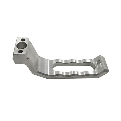
The special-shaped connecting body parts shown in Figure 1 are the key parts of a certain product firing system, and the material is 2A12-T4 aluminum alloy. The shape of the parts is complex, and programming and processing are difficult.
The part is directly processed from aluminum rods, and the material removal rate is high, and the workpiece is prone to deformation. The difficulty in processing is how to ensure the cylindricity of the arc surface between the cylindrical surface and the boss and meet the surface roughness requirements.
The process includes turning, milling, removing the process head, threading and slot milling. First, turn the blank of the special-shaped part, and then use the clamping method of one clamp and one top on the four-axis vertical machining center. The main shape of the part is processed in three steps: rough milling, semi-finishing milling and finishing milling, and then the process head is milled Go, CNC lathe double top finish thread processing, and finally mill the groove to complete the processing of the workpiece.
3 Car blanks for special-shaped parts
Figure 2 is a schematic diagram of the car sequence of special-shaped parts. The outer round stepped platform at the right end is a process chuck, and the inner hole is processed to the size of the finished product, and the other part has a processing allowance of 0.5mm on one side.

4 Milling shaped parts forming
4.1 Clamping and determining the zero point of the workpiece
Figure 3 is the zero point coordinate diagram of the workpiece. The workpiece is mounted on the fourth axis, the right end is clamped with a self-centering chuck, the left end is clamped by a plug and a tailstock with a center, and the left and right ends are small circles with a dial indicator, and the self-centering chuck is adjusted or trimmed , Control the beating of the dial indicator needle within 0.1mm, and finally lock the top.
4.2 Select the tool and determine the cutting parameters of the tool
Tool selection instructions:
1) Use large diameter tools for rough milling.
2) Use end mills for fine milling.
3) φ6mm cemented carbide cutters are mainly used for milling long grooves R3.5mm.
4) The tool diameter is mainly selected from three aspects: the size limit of the workpiece, the metal removal rate and the price of the tool.
5) When rough milling, the cutting parameters follow the principle of "shallow depth of cut, large width of cut and multi-cut fast running".
6) The selection of cutting parameters during finishing milling is mainly based on the surface roughness requirements of the workpiece. Generally speaking, the feed speed should be low and the tool penetration should be large.
7) The length specification of the tool follows the relativity theory of "one inch long and one inch short". The shorter the tool, the higher the rigidity and the more stable the cutting.
According to the above principles, the selected tool specifications and cutting parameters are shown in Table 1.
4.3 Preparation before UG8.0 programming
(1) Create 4 parent nodes, which are program creation, tool creation, geometry creation and method creation.
(2) Create process (operation) ① 3-axis 2-linkage plane milling. ②3 axis 2 linkage cavity milling. ③3 axis 2 linkage fixed axis surface contour milling. ④3~5 axis linkage variable axis surface contour milling (multi-axis milling).
(3) Create geometry (digital model) strategy ①Create (call) digital model based on the plan view, pay attention to the size of double addition or double subtraction in the plan view, generally modify the digital model to the actual size of the difference in the drawing, so that the operator can adjust the tool compensation value. ②In order to simplify the tool path, some intermittent surfaces need to be modified into a complete surface.
4.4 Rough milling profile
(1) Create the geometric zero point of the workpiece (see Figure 4). Be sure to pay attention to the safety distance setting value to prevent tool collision; the machine coordinate system setting must be accurate.
(2) Rough milling the upper and lower parts of the cavity (see Figure 5) First select "cavity milling", this function contains the main functions of cavity milling, generally used for roughing; secondly, select "in the expanded list of cavity milling" Cutting depth" function, change the cutting depth "automatic" to "manual", and change the cutting depth to 1/2 of the maximum diameter of the blank.
Figure 5 Rough milling the upper and lower parts of the cavity
(3) Rough milling of the side part (the remaining parts of the upper and lower parts of the cavity milling) (see Figure 6). The face milling must first specify the cutting area, and then give the blank distance, the cutting depth per cut and the final bottom surface allowance.
Figure 6 Rough milling of the side part
4.5 Semi-finish milling profile
(1) Basic "six toolpaths" for fixed axis milling ①Face milling: surface and bottom milling. ②Plane milling: internal and external side milling. ③ Cavity milling: bevel milling of inner and outer cavities, generally used for rough machining. ④ Residual milling: semi-finishing after cavity milling, removing margins such as corners. ⑤Depth contour milling: side contour milling, generally used for semi-precision or finishing. ⑥Profile milling of fixed-axis curved surfaces: precision milling of curved surfaces.
(2) Semi-finishing milling of the upper and lower parts and slots When semi-finishing milling, the allowance is 0.25mm. In the non-cutting movement, the method of "feeding along the oblique line of the shape, with an inclination of 5°" is adopted for the feed in the non-cutting motion. The tool is a φ8mm rough milling cutter, the feed amount t=0.5mm/layer, the feed speed vf=1000mm/min, and the rotation speed n=3000r/min. For semi-finishing milling upper and lower parts, select the "remaining milling" function; for semi-finishing slot milling (see Figure 7), select the "face milling" function.
4.6 Finish milling profile
(1) Finish milling the side of each step (see Figure 8) Select the multi-axis milling (variable-axis contour milling) function. The key options are as follows: ①The geometry is "each processing side". ②The driving method is "streamline". ③The projection vector is "toward the driving body". ④The tool is "φ8mm end mill". ⑤The tool axis is "away from the straight line".
To facilitate programming, the cross-sections of the two ears in Figure 8 have been flattened. There are many combinations of projection vector and tool axis. The above is one of them, which also shows the processing characteristics of a four-axis machining center. In this way, the side surface of the boss and the junction with the arc can be processed well.
(2) Fine milling of each arc surface also select the multi-axis milling (variable-axis contour milling) function.
① Create inspection geometry (see Figure 9). One is to prevent the tool from hitting the chuck and tailstock; the other is to prevent the tool from milling the sides of the steps.
② Create surface-driven method geometry. Create a surface and tool path as shown in Figure 10. For the surface, select the outer surface of the cylinder created, and select the horizontal direction of the arrow for the cutting direction. The arc surface is formed by the bottom of the end mill. The larger the number of steps, the higher the roundness of the circle and the larger the surface roughness value; the larger the tool diameter, the smaller the number of spacing required. There are many options for projection vector and tool axis. Here, the projection vector is "tool axis" and the tool axis is "away from the straight line".
(3) Finish milling all parts of the plane (see Figure 11) Select the face milling function. There are many tool path methods. Here, select "reciprocating", other surfaces are similar, but you need to pay attention to the direction of the tool axis, be sure to select "perpendicular to the cutting surface" or select "vector" to determine the direction of the tool axis.
4.7 Finish milling R2mm surface
For finishing R2mm surface (see Figure 12), select the fixed-axis surface contour milling function. Need to select R2mm curved surface, drive mode select "area milling", cutting mode select "reciprocating", cloth distance select "constant", maximum distance given 0.1mm, tool axis direction select "designated vector".
4.8 Finish milling the surface with dimensional tolerance requirements
Figure 13 shows the finish milling of the surface with dimensional tolerance requirements. Generally, the size requirements cannot be met at one time, and multiple processing is required. It is necessary to create a program separately and select the tool "compensation function" to facilitate the operator to adjust the processing size on site.
5 Milling off the process head
Figure 14 shows the milling process head, select the "contour milling" function. In order to facilitate programming, the process head needs to be changed to square, select "mixed milling", "depth priority", transfer type to "direct", cutting parameters: speed n = 3000r/min, feed speed vf = 1500mm/min, feed The amount t=0.25mm/layer. In this way, the processing concept of "light cutting and fast running" can be realized to prevent deformation of the workpiece.
6 threading
Figure 15 shows threading. Self-made special plug, CNC lathe double top clamping workpiece.
7 Slot milling
Figure 16 shows slot milling. To mill arc surface grooves, you need to create a plane and project the contour of the groove on the plane. Choose plane milling and use the "light cut and fast run" method to prevent deformation of the workpiece.
8 concluding remarks
If the above processing cases are carried out on ordinary equipment, a lot of jigs and fixtures need to be made, which takes several weeks, and it is difficult to realize the arc surface processing between the cylinder and the boss. The manufacturing time of CNC machining is only about 14h, and the quality of the workpiece fully meets the drawing requirements.
Link to this article: Numerical control machining of complex and special-shaped parts
Reprint Statement: If there are no special instructions, all articles on this site are original. Please indicate the source for reprinting:https://www.cncmachiningptj.com/,thanks!
 3, 4 and 5-axis precision CNC machining services for aluminum machining, beryllium, carbon steel, magnesium, titanium machining, Inconel, platinum, superalloy, acetal, polycarbonate, fiberglass, graphite and wood. Capable of machining parts up to 98 in. turning dia. and +/-0.001 in. straightness tolerance. Processes include milling, turning, drilling, boring, threading, tapping, forming, knurling, counterboring, countersinking, reaming and laser cutting. Secondary services such as assembly, centerless grinding, heat treating, plating and welding. Prototype and low to high volume production offered with maximum 50,000 units. Suitable for fluid power, pneumatics, hydraulics and valve applications. Serves the aerospace, aircraft, military, medical and defense industries.PTJ will strategize with you to provide the most cost-effective services to help you reach your target,Welcome to Contact us ( [email protected] ) directly for your new project.

- 5 Axis Machining
- Cnc Milling
- Cnc Turning
- Machining Industries
- Machining Process
- Surface Treatment
- Metal Machining
- Plastic Machining
- Powder Metallurgy Mold
- Die Casting
- Parts Gallery
- Auto Metal Parts
- Machinery Parts
- LED Heatsink
- Building Parts
- Mobile Parts
- Medical Parts
- Electronic Parts
- Tailored Machining
- Bicycle Parts
- Aluminum Machining
- Titanium Machining
- Stainless Steel Machining
- Copper Machining
- Brass Machining
- Super Alloy Machining
- Peek Machining
- UHMW Machining
- Unilate Machining
- PA6 Machining
- PPS Machining
- Teflon Machining
- Inconel Machining
- Tool Steel Machining
- More Material