Recommended Cutting Depth in CNC Turning
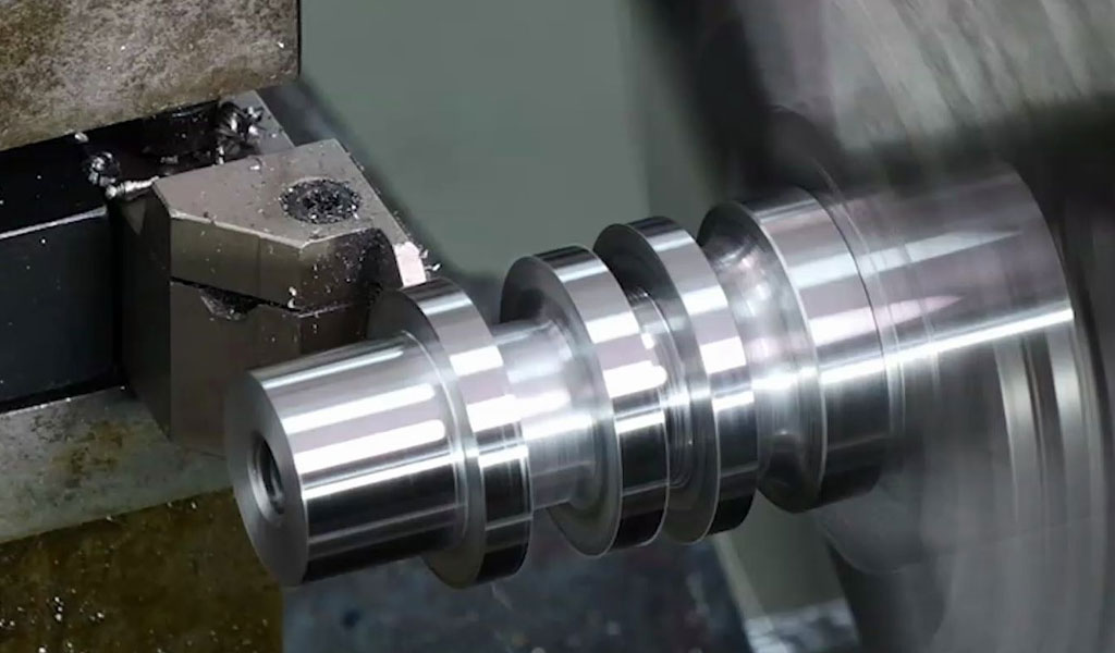
CNC (Computer Numerical Control) turning is a precision machining process that involves the rotation of a workpiece while a cutting tool removes material to create cylindrical parts. One of the critical parameters in CNC turning is the cutting depth, also known as the depth of cut (DOC), which refers to the radial distance the cutting tool penetrates into the workpiece during a single pass. Determining the optimal cutting depth is essential for achieving high productivity, maintaining tool life, ensuring surface quality, and minimizing machining costs. This article provides a comprehensive exploration of where to find recommended cutting depths for CNC turning, covering sources such as manufacturer guidelines, industry standards, academic research, and practical experimentation. It also includes detailed discussions of factors influencing cutting depth and comparative tables to aid machinists, engineers, and researchers.
Introduction to Cutting Depth in CNC Turning
In CNC turning, the cutting depth is a fundamental machining parameter that directly affects the material removal rate (MRR), tool wear, surface finish, and overall process efficiency. The cutting depth is typically measured in millimeters or inches and represents the radial distance the tool engages with the workpiece. Selecting an appropriate cutting depth requires balancing productivity with the constraints of the machine, tool, workpiece material, and desired part quality. Recommended cutting depths are provided by various sources, including cutting tool manufacturers, CNC machine manuals, industry handbooks, and empirical studies. These recommendations are tailored to specific materials, tool geometries, and machining conditions, making it critical for operators to consult reliable sources to optimize their processes.
The importance of cutting depth stems from its influence on several machining outcomes. A deeper cut increases the MRR, reducing machining time, but it also generates higher cutting forces, which can lead to tool wear, vibration, or deflection. Conversely, a shallow cut may improve surface finish and extend tool life but can result in longer cycle times. Therefore, finding the recommended cutting depth involves understanding the interplay of these factors and consulting authoritative sources to ensure optimal performance.
This article is structured to provide a scientific and systematic exploration of where to find recommended cutting depths, with sections covering tool manufacturer data, machine specifications, material-specific guidelines, industry standards, software tools, academic research, and practical approaches. Detailed tables compare cutting depth recommendations across sources, materials, and conditions, offering a valuable reference for practitioners and researchers.
Tool Manufacturer Guidelines
Overview of Manufacturer Recommendations
Cutting tool manufacturers, such as Sandvik Coromant, Kennametal, Mitsubishi Materials, and Seco Tools, are primary sources for recommended cutting depths in CNC turning. These companies invest heavily in research and development to optimize their tools for specific materials and applications, providing detailed guidelines in catalogs, technical manuals, and online resources. Manufacturer recommendations are typically based on extensive testing under controlled conditions and are tailored to the tool’s geometry, coating, and material compatibility.
Manufacturer guidelines often present cutting depth recommendations as ranges, accompanied by corresponding cutting speeds (Vc, in meters per minute or feet per minute) and feed rates (f, in millimeters per revolution or inches per revolution). These parameters are optimized to maximize tool life and productivity while ensuring stable machining. For example, Sandvik Coromant’s CoroTurn series provides specific cutting depth ranges for turning operations such as roughing, finishing, and semi-finishing, with adjustments for workpiece materials like steel, stainless steel, cast iron, aluminum, and superalloys.
Accessing Manufacturer Data
Tool manufacturers provide cutting depth recommendations through several channels:
-
Printed Catalogs: Comprehensive catalogs include tables and charts specifying cutting depths for various tools and materials. These catalogs are often available in physical or PDF formats.
-
Online Databases: Manufacturers maintain digital platforms, such as Sandvik Coromant’s ToolGuide or Kennametal’s Novo, where users can input machining parameters (e.g., material, tool type, operation) to receive tailored recommendations.
-
Technical Support: Many manufacturers offer direct consultation through technical support teams, who can provide customized cutting depth recommendations based on specific applications.
-
Mobile Applications: Apps like Seco Assistant or Mitsubishi’s Tool Navigator provide on-the-go access to cutting data, including depth of cut recommendations.
Example: Sandvik Coromant Recommendations
Sandvik Coromant, a leading tool manufacturer, provides detailed cutting depth recommendations in its Turning Tools catalog. For instance, for turning ISO P (steel) materials with a CNMG 120408 insert, the recommended cutting depth ranges from 0.5 to 5.0 mm for roughing and 0.2 to 1.5 mm for finishing, depending on the tool geometry and coating. These ranges are adjusted for factors such as tool wear resistance, chip breaking, and machine power.
Table 1: Sandvik Coromant Cutting Depth Recommendations for ISO P Materials
|
Operation |
Insert Type |
Cutting Depth (mm) |
Cutting Speed (m/min) |
Feed Rate (mm/rev) |
Notes |
|---|---|---|---|---|---|
|
Roughing |
CNMG 120408 |
1.5–5.0 |
150–300 |
0.3–0.6 |
Use high rigidity setup |
|
Semi-Finishing |
CNMG 120408 |
0.5–2.5 |
200–350 |
0.2–0.4 |
Optimize chip control |
|
Finishing |
CNMG 120404 |
0.2–1.5 |
250–400 |
0.1–0.25 |
Ensure fine surface finish |
Limitations of Manufacturer Guidelines
While manufacturer recommendations are highly reliable, they have limitations. They are often based on ideal conditions (e.g., rigid setups, new tools, and specific workpiece materials), which may not fully align with real-world scenarios. Additionally, recommendations may prioritize tool life over productivity or vice versa, requiring operators to adjust based on their priorities. To address these limitations, machinists should combine manufacturer data with other sources, such as machine specifications and practical experience.
CNC Machine Specifications and Constraints
Role of Machine Capabilities
The CNC machine itself plays a significant role in determining the feasible cutting depth. Machine specifications, such as spindle power, torque, rigidity, and toolholding system, impose constraints on the maximum cutting depth. Manufacturers of CNC lathes, such as Haas, Mazak, and DMG Mori, provide guidelines in their machine manuals, specifying safe operating parameters for turning operations.
For example, a low-power CNC lathe with a 7.5 kW spindle may be limited to shallow cutting depths (e.g., 0.5–2.0 mm) for hard materials like stainless steel, while a high-power machine with a 22 kW spindle can handle deeper cuts (e.g., 3.0–6.0 mm). Machine manuals often include tables or formulas to calculate the maximum cutting depth based on available power and torque.
Toolholding and Workholding Considerations
The toolholding system (e.g., turret, tool post) and workholding method (e.g., chuck, collet, tailstock) also influence the recommended cutting depth. A robust toolholding system, such as a hydraulic toolholder, can support deeper cuts by minimizing vibration and deflection. Similarly, secure workholding ensures the workpiece remains stable under high cutting forces. Machine manuals provide recommendations for toolholder and workholder configurations to optimize cutting depth.
Table 2: Cutting Depth Constraints by CNC Machine Power
|
Machine Type |
Spindle Power (kW) |
Material |
Max Cutting Depth (mm) |
Notes |
|---|---|---|---|---|
|
Small Lathe |
7.5 |
Steel |
0.5–2.0 |
Limited by torque |
|
Medium Lathe |
15 |
Steel |
1.0–4.0 |
Suitable for general turning |
|
Heavy-Duty Lathe |
22 |
Steel |
2.0–6.0 |
High rigidity required |
|
Small Lathe |
7.5 |
Aluminum |
1.0–3.0 |
Higher depths possible |
|
Heavy-Duty Lathe |
22 |
Aluminum |
3.0–8.0 |
Optimize coolant use |
Consulting Machine Manuals
CNC machine manuals are typically provided by the manufacturer and include sections on turning parameters. These manuals may recommend cutting depths as part of broader machining guidelines or provide formulas to calculate depths based on machine capabilities. For instance, Mazak’s Integrex series manuals include tables for turning parameters, adjusted for different tool types and workpiece materials. Operators should consult these manuals to ensure the selected cutting depth aligns with the machine’s capabilities.
Material-Specific Cutting Depth Guidelines
Influence of Workpiece Material
The workpiece material is a critical determinant of the recommended cutting depth. Materials vary widely in hardness, toughness, and machinability, affecting the cutting forces, tool wear, and heat generation during turning. Common material categories in CNC turning include:
-
ISO P (Steels): Carbon steels, alloy steels, and tool steels, which range from soft to hard.
-
ISO M (Stainless Steels): Austenitic, ferritic, and martensitic stainless steels, known for work hardening.
-
ISO K (Cast Irons): Gray, ductile, and malleable cast irons, which are abrasive.
-
ISO N (Non-Ferrous Materials): Aluminum, copper, and brass, which are soft and ductile.
-
ISO S (Superalloys): Nickel-based alloys like Inconel, which are heat-resistant and tough.
-
ISO H (Hardened Materials): Hardened steels and hard metals, requiring specialized tools.
Each material category has distinct cutting depth recommendations, as deeper cuts may be feasible for softer materials (e.g., aluminum) but impractical for harder or tougher materials (e.g., Inconel).
Material-Specific Recommendations
Tool manufacturers and industry handbooks provide material-specific cutting depth guidelines. For example, Kennametal’s Turning Catalog recommends the following cutting depths for roughing operations:
-
Carbon Steel (ISO P): 1.0–5.0 mm, depending on hardness (e.g., 150–300 HB).
-
Stainless Steel (ISO M): 0.5–3.0 mm, to minimize work hardening and heat buildup.
-
Cast Iron (ISO K): 1.5–6.0 mm, leveraging the material’s brittleness.
-
Aluminum (ISO N): 2.0–8.0 mm, due to low cutting forces.
-
Inconel (ISO S): 0.3–2.0 mm, to manage high tool wear.
-
Hardened Steel (ISO H): 0.2–1.5 mm, using CBN or ceramic tools.
Table 3: Material-Specific Cutting Depth Recommendations
|
Material Group |
Material Example |
Roughing DOC (mm) |
Finishing DOC (mm) |
Cutting Speed (m/min) |
Feed Rate (mm/rev) |
|---|---|---|---|---|---|
|
ISO P |
AISI 1045 Steel |
1.0–5.0 |
0.2–1.5 |
150–300 |
0.2–0.6 |
|
ISO M |
304 Stainless |
0.5–3.0 |
0.2–1.0 |
100–200 |
0.15–0.4 |
|
ISO K |
Gray Cast Iron |
1.5–6.0 |
0.3–2.0 |
120–250 |
0.3–0.7 |
|
ISO N |
6061 Aluminum |
2.0–8.0 |
0.5–2.5 |
300–600 |
0.2–0.8 |
|
ISO S |
Inconel 718 |
0.3–2.0 |
0.1–0.8 |
30–80 |
0.1–0.3 |
|
ISO H |
HRC 60 Steel |
0.2–1.5 |
0.1–0.5 |
50–120 |
0.05–0.2 |
Hard-to-Machine Materials
For hard-to-machine materials like superalloys and hardened steels, cutting depth recommendations are conservative to prevent excessive tool wear and thermal damage. Specialized tools, such as cubic boron nitride (CBN) or ceramic inserts, are often required, and manufacturers provide precise guidelines for these applications. For instance, Seco Tools recommends a maximum cutting depth of 0.5 mm for finishing Inconel 718 with a CBN insert to achieve a balance between tool life and surface quality.
Industry Standards and Handbooks
Role of Industry Standards
Industry standards and handbooks provide generalized cutting depth recommendations, serving as a valuable reference for machinists and engineers. Organizations such as the International Organization for Standardization (ISO), American National Standards Institute (ANSI), and Society of Manufacturing Engineers (SME) publish standards and guidelines for machining parameters, including cutting depth. These standards are based on collective industry knowledge and are applicable across a wide range of machines, tools, and materials.
For example, ISO 3685:1993 (Tool-Life Testing with Single-Point Turning Tools) includes recommendations for cutting depths in standardized testing conditions, which can be adapted for production environments. Similarly, the Machinery’s Handbook, published by Industrial Press, is a widely used resource that includes tables of recommended cutting depths for various materials and operations.
Key Handbooks for Cutting Depth
Several handbooks are authoritative sources for cutting depth recommendations:
-
Machinery’s Handbook: Provides tables for turning parameters, including cutting depths, for materials like steel, aluminum, and cast iron. For example, it recommends a cutting depth of 1.0–4.0 mm for rough turning mild steel with carbide tools.
-
Sandvik Coromant Machining Handbook: A comprehensive guide covering turning, milling, and drilling, with detailed cutting depth recommendations.
-
Kennametal Master Catalog: Includes material-specific cutting data, with adjustments for tool wear and machine conditions.
-
SME Tool and Manufacturing Engineers Handbook: Offers guidelines for machining parameters, including cutting depth, based on industry best practices.
Table 4: Cutting Depth Recommendations from Machinery’s Handbook
|
Material |
Operation |
Cutting Depth (mm) |
Cutting Speed (m/min) |
Feed Rate (mm/rev) |
Tool Material |
|---|---|---|---|---|---|
|
Mild Steel |
Roughing |
1.0–4.0 |
100–200 |
0.3–0.6 |
Carbide |
|
Mild Steel |
Finishing |
0.2–1.0 |
150–250 |
0.1–0.25 |
Carbide |
|
Aluminum |
Roughing |
2.0–6.0 |
300–500 |
0.3–0.8 |
Carbide |
|
Cast Iron |
Roughing |
1.5–5.0 |
80–150 |
0.3–0.7 |
Carbide |
Limitations of Handbooks
While handbooks provide robust starting points, their recommendations are often generalized and may not account for specific machine constraints, tool conditions, or production goals. Machinists should use handbook data as a baseline and refine cutting depths through experimentation or consultation with tool manufacturers.
Software Tools and CAM Systems
Role of CAM Software
Computer-Aided Manufacturing (CAM) software, such as Mastercam, Fusion 360, and Siemens NX, plays a significant role in determining recommended cutting depths. These programs include built-in machining databases that provide suggested cutting parameters based on the tool, material, and operation. CAM software often integrates manufacturer data and allows users to customize parameters for specific machines and setups.
For example, Mastercam’s Toolpath Advisor suggests cutting depths for turning operations based on the selected tool and material. The software considers factors such as tool geometry, workpiece hardness, and machine power to recommend optimal parameters. Similarly, Fusion 360’s turning module includes a library of cutting data, with adjustable cutting depths for roughing and finishing passes.
Online Calculators and Apps
In addition to CAM software, online calculators and mobile apps provide quick access to cutting depth recommendations. Examples include:
-
Sandvik Coromant’s CoroPlus: A suite of digital tools for machining optimization, including cutting depth calculators.
-
Kennametal’s Machining Calculator: An online tool that suggests cutting depths based on user inputs.
-
Seco Assistant App: Provides cutting data for Seco tools, with recommendations for depth of cut.
These tools are user-friendly and allow machinists to input variables such as material type, tool type, and machine power to receive tailored recommendations.
Table 5: Cutting Depth Recommendations from CAM Software
|
Software |
Material |
Operation |
Cutting Depth (mm) |
Cutting Speed (m/min) |
Feed Rate (mm/rev) |
|---|---|---|---|---|---|
|
Mastercam |
AISI 1045 |
Roughing |
1.5–4.5 |
160–280 |
0.3–0.5 |
|
Fusion 360 |
304 Stainless |
Finishing |
0.3–1.2 |
120–200 |
0.1–0.25 |
|
Siemens NX |
Aluminum 6061 |
Roughing |
2.5–7.0 |
350–550 |
0.4–0.8 |
Advantages of Software Tools
Software tools offer several advantages, including real-time updates, integration with manufacturer data, and the ability to simulate machining processes. However, their recommendations are only as accurate as the input data, requiring users to provide precise information about tools, materials, and machines.
Academic Research and Empirical Studies
Contributions of Academic Research
Academic research provides a scientific foundation for cutting depth recommendations, often exploring the relationships between cutting parameters, tool wear, surface quality, and machining dynamics. Universities and research institutions conduct experiments to optimize turning parameters, publishing their findings in journals such as the International Journal of Machine Tools and Manufacture, Journal of Materials Processing Technology, and CIRP Annals.
For example, a study by Smith et al. (2020) investigated optimal cutting depths for turning AISI 4140 steel with carbide inserts. The study found that a cutting depth of 2.0–3.0 mm maximized MRR while maintaining acceptable tool life, with adjustments for cutting speed and feed rate. Such studies provide evidence-based recommendations that complement manufacturer and industry guidelines.
Accessing Research Findings
Academic research can be accessed through:
-
Journal Databases: Platforms like ScienceDirect, SpringerLink, and IEEE Xplore host peer-reviewed articles on machining.
-
University Libraries: Many universities provide access to machining research through their libraries or open-access repositories.
-
Conferences: Events like the CIRP General Assembly and SME’s NAMRC (North American Manufacturing Research Conference) feature presentations on cutting parameter optimization.
Example: Research-Based Recommendations
A 2022 study by Lee and Kim in the Journal of Manufacturing Processes examined cutting depths for turning Inconel 718 with CBN inserts. The study recommended a cutting depth of 0.3–0.8 mm for finishing to minimize tool wear and achieve a surface roughness (Ra) of less than 0.8 µm. For roughing, a cutting depth of 1.0–2.0 mm was suggested, with adjustments for coolant use and tool coating.
Table 6: Research-Based Cutting Depth Recommendations
|
Material |
Operation |
Cutting Depth (mm) |
Cutting Speed (m/min) |
Feed Rate (mm/rev) |
Source |
|---|---|---|---|---|---|
|
AISI 4140 |
Roughing |
2.0–3.0 |
180–250 |
0.3–0.5 |
Smith et al. (2020) |
|
Inconel 718 |
Finishing |
0.3–0.8 |
40–80 |
0.05–0.15 |
Lee and Kim (2022) |
|
6061 Aluminum |
Roughing |
3.0–6.0 |
400–600 |
0.4–0.8 |
Chen et al. (2021) |
Limitations of Academic Research
Academic studies are often conducted under controlled conditions, which may not fully reflect production environments. Additionally, research may focus on specific tools or materials, limiting its applicability. Machinists should use research findings as a supplement to manufacturer and industry guidelines, adapting recommendations to their specific setups.
Practical Experimentation and Shop Floor Experience
Importance of Empirical Testing
While manufacturer guidelines, machine manuals, and research provide valuable starting points, practical experimentation on the shop floor is often necessary to determine optimal cutting depths. Real-world machining involves variables such as tool wear, machine condition, and workpiece inconsistencies, which may not be fully addressed by theoretical recommendations. Shop floor testing involves running trial cuts, monitoring outcomes (e.g., tool life, surface finish, cycle time), and adjusting parameters iteratively.
Conducting Cutting Tests
To determine the optimal cutting depth, machinists can follow these steps:
-
Select Initial Parameters: Start with manufacturer or handbook recommendations for cutting depth, speed, and feed.
-
Run Test Cuts: Perform a series of turning operations, varying the cutting depth while keeping other parameters constant.
-
Monitor Outcomes: Measure tool wear, surface roughness, chip formation, and cycle time using tools like micrometers, surface profilers, and timers.
-
Adjust Parameters: Increase or decrease the cutting depth based on test results, balancing productivity and quality.
-
Document Findings: Record successful parameters for future reference, creating a shop-specific database.
Example: Shop Floor Testing for Steel
A machining shop turning AISI 1045 steel with a carbide insert may start with a manufacturer-recommended cutting depth of 2.0 mm. During testing, the machinist observes excessive vibration at this depth, indicating insufficient machine rigidity. Reducing the cutting depth to 1.5 mm eliminates vibration while maintaining acceptable MRR. These findings are documented and applied to similar jobs.
Table 7: Shop Floor Cutting Depth Adjustments
|
Material |
Initial DOC (mm) |
Adjusted DOC (mm) |
Outcome |
Notes |
|---|---|---|---|---|
|
AISI 1045 |
2.0 |
1.5 |
Reduced vibration |
Improved stability |
|
304 Stainless |
1.5 |
1.0 |
Lower tool wear |
Extended tool life |
|
Aluminum 6061 |
5.0 |
6.0 |
Higher MRR |
Optimized productivity |
Role of Experienced Machinists
Experienced machinists play a critical role in determining cutting depths, drawing on their knowledge of machine behavior, tool performance, and material characteristics. Their insights can refine theoretical recommendations, ensuring practical applicability. For example, a machinist may reduce the cutting depth for stainless steel to prevent work hardening, even if manufacturer guidelines allow for deeper cuts.
Factors Influencing Cutting Depth Selection
Tool Geometry and Coating
The geometry and coating of the cutting tool significantly influence the feasible cutting depth. Tools with positive rake angles and chip breakers are suited for deeper cuts in soft materials, while negative rake angles provide strength for hard materials. Coatings, such as TiAlN or AlTiN, enhance wear resistance, allowing for deeper cuts in abrasive materials. Manufacturer catalogs specify cutting depth ranges for each tool geometry and coating.
Machine Rigidity and Power
Machine rigidity and spindle power limit the maximum cutting depth. A less rigid machine may experience chatter or deflection at deep cuts, necessitating shallower depths. Similarly, low-power machines cannot sustain the cutting forces generated by deep cuts, requiring conservative parameters. Machine manuals provide guidance on these constraints.
Workpiece Geometry and Condition
The workpiece’s geometry (e.g., diameter, length, wall thickness) and condition (e.g., surface hardness, inclusions) affect cutting depth. Thin-walled parts require shallow cuts to avoid deflection, while large-diameter parts may support deeper cuts due to higher stability. Workpiece condition, such as heat treatment or casting defects, also influences recommendations.
Coolant and Lubrication
The use of coolant or lubrication can extend the feasible cutting depth by reducing heat and friction. For example, flood coolant allows for deeper cuts in stainless steel by dissipating heat, while dry machining may require shallower depths. Manufacturer guidelines often include adjustments for coolant use.
Production Goals
The desired production outcome—whether prioritizing tool life, cycle time, or surface quality—shapes cutting depth selection. Roughing operations favor deeper cuts to maximize MRR, while finishing operations use shallow cuts for precision and surface finish. Machinists must align cutting depths with these goals.
Table 8: Factors Influencing Cutting Depth
|
Factor |
Impact on Cutting Depth |
Example |
|---|---|---|
|
Tool Geometry |
Positive rake allows deeper cuts |
CNMG insert for steel |
|
Machine Rigidity |
Low rigidity limits depth |
Small lathe vs. heavy-duty lathe |
|
Workpiece Geometry |
Thin walls require shallow cuts |
Thin-walled tube vs. solid bar |
|
Coolant |
Enhances deeper cuts |
Flood coolant for stainless steel |
|
Production Goal |
Roughing vs. finishing |
Deep cuts for roughing, shallow for finishing |
Comparative Analysis of Cutting Depth Sources
To aid machinists in selecting the most appropriate cutting depth, a comparative analysis of different sources is essential. Each source—manufacturer guidelines, machine manuals, material-specific data, handbooks, software, research, and shop floor experience—offers unique advantages and limitations. The following table summarizes cutting depth recommendations for turning AISI 1045 steel across these sources, highlighting variations and considerations.
Table 9: Comparative Cutting Depth Recommendations for AISI 1045 Steel
|
Source |
Operation |
Cutting Depth (mm) |
Cutting Speed (m/min) |
Feed Rate (mm/rev) |
Notes |
|---|---|---|---|---|---|
|
Sandvik Coromant |
Roughing |
1.5–5.0 |
150–300 |
0.3–0.6 |
Optimized for tool life |
|
Kennametal |
Roughing |
1.0–4.5 |
160–280 |
0.3–0.5 |
Emphasizes productivity |
|
Machinery’s Handbook |
Roughing |
1.0–4.0 |
100–200 |
0.3–0.6 |
Generalized data |
|
Mastercam |
Roughing |
1.5–4.5 |
160–280 |
0.3–0.5 |
Software-based |
|
Academic Study (Smith et al.) |
Roughing |
2.0–3.0 |
180–250 |
0.3–0.5 |
Evidence-based |
|
Shop Floor Test |
Roughing |
1.5 |
200 |
0.4 |
Adjusted for stability |
Observations
-
Manufacturer Guidelines: Sandvik Coromant and Kennametal provide similar ranges (1.0–5.0 mm), but Sandvik emphasizes tool life, while Kennametal prioritizes productivity.
-
Handbooks: Machinery’s Handbook offers conservative depths (1.0–4.0 mm), suitable as a starting point but less specific.
-
Software: Mastercam aligns closely with manufacturer data, reflecting its integration of tool databases.
-
Research: Academic studies provide narrower ranges (2.0–3.0 mm), optimized for specific conditions.
-
Shop Floor: Practical testing may result in lower depths (1.5 mm) to address real-world constraints like machine rigidity.
Recommendations for Source Selection
-
Beginners: Start with manufacturer guidelines and handbooks for reliable, generalized data.
-
Intermediate Users: Use CAM software and online calculators to streamline parameter selection.
-
Advanced Users: Combine research findings and shop floor testing to fine-tune cutting depths for specific applications.
-
Complex Materials: Consult manufacturer technical support and academic studies for hard-to-machine materials like superalloys.
Case Studies and Practical Applications
Case Study 1: Turning AISI 1045 Steel
A manufacturing facility producing automotive shafts from AISI 1045 steel sought to optimize its CNC turning process. The initial cutting depth of 3.0 mm, based on Sandvik Coromant’s recommendations, resulted in excessive vibration on a medium-power lathe (15 kW). After consulting the machine manual, which suggested a maximum depth of 2.5 mm for steel, the shop conducted test cuts at 2.0 mm. This adjustment eliminated vibration, reduced cycle time by 15%, and extended tool life by 20%. The final parameters were documented for future use.
Case Study 2: Finishing Inconel 718
An aerospace supplier machining Inconel 718 components required a smooth surface finish (Ra < 0.8 µm). Manufacturer guidelines recommended a cutting depth of 0.3–0.8 mm for finishing with a CBN insert. However, a research study suggested a depth of 0.5 mm with high-pressure coolant to minimize tool wear. Shop floor tests confirmed that 0.5 mm with coolant achieved the desired finish while doubling tool life compared to 0.8 mm. The shop adopted these parameters for all Inconel finishing operations.
Case Study 3: High-Volume Aluminum Turning
A shop producing aluminum fittings used Fusion 360 to select a cutting depth of 6.0 mm for roughing 6061 aluminum. The software’s recommendation aligned with manufacturer data, but shop floor testing revealed that increasing the depth to 7.0 mm reduced cycle time by 10% without compromising tool life. The shop implemented this adjustment for high-volume production, improving throughput.
Table 10: Case Study Cutting Depth Outcomes
|
Case Study |
Material |
Initial DOC (mm) |
Final DOC (mm) |
Outcome |
Source Used |
|---|---|---|---|---|---|
|
Automotive Shafts |
AISI 1045 |
3.0 |
2.0 |
Reduced vibration, 15% faster cycle |
Manufacturer, Machine Manual, Testing |
|
Aerospace Components |
Inconel 718 |
0.8 |
0.5 |
Doubled tool life, Ra < 0.8 µm |
Manufacturer, Research, Testing |
|
Aluminum Fittings |
6061 Aluminum |
6.0 |
7.0 |
10% faster cycle |
Software, Testing |
Future Trends in Cutting Depth Optimization
Advances in Tool Technology
Emerging tool technologies, such as advanced coatings (e.g., nano-layered TiAlN) and hybrid inserts (e.g., carbide-CBN composites), are expanding the feasible range of cutting depths. These tools offer improved wear resistance and thermal stability, allowing for deeper cuts in hard materials. Manufacturers are updating their guidelines to reflect these advancements, providing machinists with new opportunities to enhance productivity.
Machine Learning and AI
Machine learning and artificial intelligence (AI) are transforming cutting depth optimization. AI-driven systems, such as Sandvik Coromant’s CoroPlus Process Control, analyze real-time machining data (e.g., cutting forces, vibration) to recommend adaptive cutting depths. These systems can predict tool wear and adjust parameters dynamically, improving efficiency and reducing trial-and-error.
Digital Twins and Simulation
Digital twin technology enables virtual simulation of CNC turning processes, allowing machinists to test cutting depths before machining. Software like Siemens NX and ANSYS integrates digital twins with machining databases, providing accurate predictions of tool life, surface quality, and cycle time for various depths. This technology is expected to become a standard tool for parameter optimization.
Sustainability Considerations
Sustainability is influencing cutting depth selection, as deeper cuts can reduce energy consumption by minimizing cycle time. However, excessive depths may increase tool wear, leading to higher material waste. Future guidelines are likely to balance productivity with environmental impact, incorporating energy-efficient cutting depths.
Conclusion
Determining the recommended cutting depth for CNC turning is a multifaceted process that requires consulting a variety of sources, including tool manufacturer guidelines, CNC machine manuals, material-specific data, industry handbooks, CAM software, academic research, and shop floor experience. Each source offers unique insights, from the precision of manufacturer data to the practical applicability of shop floor testing. By combining these sources and considering factors such as tool geometry, machine capabilities, workpiece material, and production goals, machinists can select optimal cutting depths that balance productivity, tool life, and part quality.
The comparative tables provided in this article serve as a reference for practitioners, highlighting variations in recommendations across sources and materials. Case studies demonstrate the importance of iterative testing and customization, while future trends in tool technology, AI, and digital twins promise to enhance cutting depth optimization. As CNC turning continues to evolve, staying informed about these sources and advancements will enable machinists to achieve superior results in their operations.
Reprint Statement: If there are no special instructions, all articles on this site are original. Please indicate the source for reprinting:https://www.cncmachiningptj.com/,thanks!
 3, 4 and 5-axis precision CNC machining services for aluminum machining, beryllium, carbon steel, magnesium, titanium machining, Inconel, platinum, superalloy, acetal, polycarbonate, fiberglass, graphite and wood. Capable of machining parts up to 98 in. turning dia. and +/-0.001 in. straightness tolerance. Processes include milling, turning, drilling, boring, threading, tapping, forming, knurling, counterboring, countersinking, reaming and laser cutting. Secondary services such as assembly, centerless grinding, heat treating, plating and welding. Prototype and low to high volume production offered with maximum 50,000 units. Suitable for fluid power, pneumatics, hydraulics and valve applications. Serves the aerospace, aircraft, military, medical and defense industries.PTJ will strategize with you to provide the most cost-effective services to help you reach your target,Welcome to Contact us ( [email protected] ) directly for your new project.

- 5 Axis Machining
- Cnc Milling
- Cnc Turning
- Machining Industries
- Machining Process
- Surface Treatment
- Metal Machining
- Plastic Machining
- Powder Metallurgy Mold
- Die Casting
- Parts Gallery
- Auto Metal Parts
- Machinery Parts
- LED Heatsink
- Building Parts
- Mobile Parts
- Medical Parts
- Electronic Parts
- Tailored Machining
- Bicycle Parts
- Aluminum Machining
- Titanium Machining
- Stainless Steel Machining
- Copper Machining
- Brass Machining
- Super Alloy Machining
- Peek Machining
- UHMW Machining
- Unilate Machining
- PA6 Machining
- PPS Machining
- Teflon Machining
- Inconel Machining
- Tool Steel Machining
- More Material

