Interference Processing in Surface Discrete CNC Machining
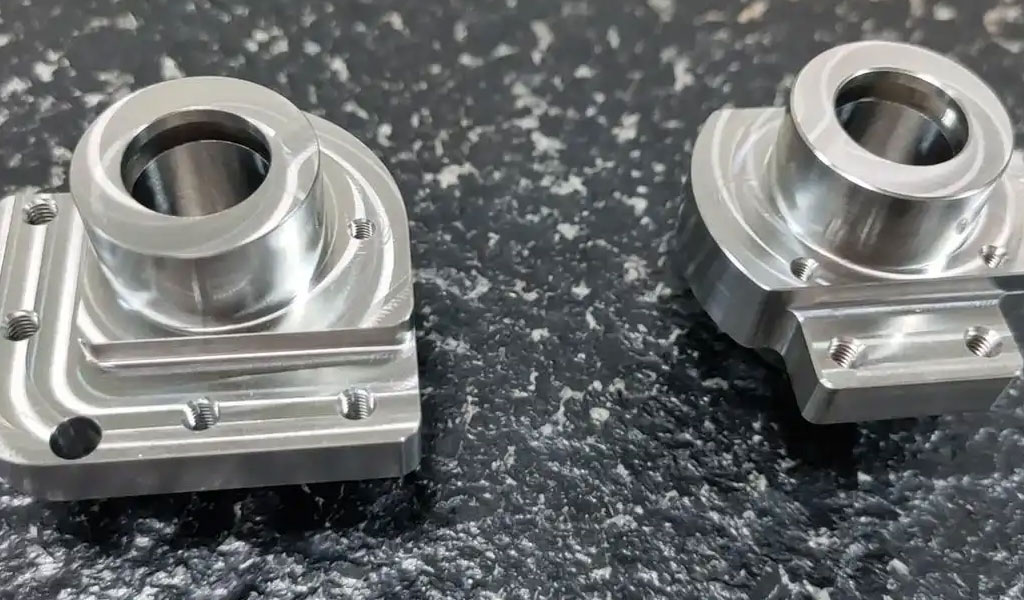
Computer Numerical Control (CNC) machining is a cornerstone of modern manufacturing, enabling the precise fabrication of complex geometries across industries such as aerospace, automotive, medical, and consumer electronics. Among the challenges in CNC machining, particularly in the context of surface discrete machining, interference processing stands out as a critical issue that affects both the quality of the machined part and the efficiency of the manufacturing process. Interference, often referred to as gouging or collision, occurs when the cutting tool inadvertently removes material beyond the intended design or collides with the workpiece, machine components, or fixtures. This article provides a comprehensive exploration of interference processing in surface discrete CNC machining, covering its theoretical foundations, detection and avoidance strategies, recent advancements, and practical applications. Detailed tables are included to compare methodologies, technologies, and outcomes based on recent research and industry practices.
Introduction to Surface Discrete CNC Machining
Surface discrete CNC machining involves the fabrication of complex, freeform, or sculptured surfaces by discretizing the surface into a series of cutter location (CL) points and tool paths. These surfaces, often characterized by non-uniform rational B-spline (NURBS) or parametric representations, are prevalent in industries requiring high precision, such as aerospace for turbine blades or automotive for mold and die production. Unlike traditional machining of prismatic parts, surface discrete machining deals with continuous, curved geometries where tool paths are generated based on discrete points rather than continuous analytical surfaces.
The process begins with a computer-aided design (CAD) model, which is processed through computer-aided manufacturing (CAM) software to generate tool paths. These tool paths consist of a sequence of CL points, each defining the position and orientation of the tool. In five-axis CNC machining, the tool’s orientation can be adjusted along two rotational axes, adding complexity to tool path planning but enabling greater flexibility in machining intricate surfaces. However, this complexity introduces the risk of interference, where the tool, tool holder, or machine components inadvertently interact with the workpiece or other elements, leading to surface defects, tool damage, or machine failure.
Interference in surface discrete CNC machining can be broadly categorized into three types: local gouging, rear gouging, and global interference. Local gouging occurs when the tool’s cutting edge removes material beyond the intended surface due to a mismatch between the tool’s radius and the surface’s curvature. Rear gouging happens when the non-cutting portions of the tool, such as the tool’s bottom or flank, contact the workpiece. Global interference involves collisions between the tool, tool holder, or machine components and the workpiece or fixtures. Addressing these issues requires sophisticated detection and avoidance strategies, which are the focus of this article.
Theoretical Foundations of Interference in CNC Machining
Geometric Considerations in Surface Discrete Machining
In surface discrete CNC machining, the tool path is generated based on a discretized representation of the surface, typically as a point cloud or a mesh of triangles. Each CL point specifies the tool’s position (x, y, z coordinates) and orientation (defined by angles such as lead and tilt in five-axis machining). The tool path is planned to ensure that the tool’s cutting edge follows the desired surface contour while maintaining specified tolerances, such as scallop height or surface roughness.
The geometry of the tool and workpiece plays a critical role in interference. Common tool types include ball-end mills, flat-end mills, and torus mills, each with distinct geometric properties. Ball-end mills, for instance, are widely used for sculptured surfaces due to their spherical cutting edge, which simplifies positioning on curved surfaces. However, their curvature can lead to local gouging if the tool’s radius exceeds the surface’s minimum radius of curvature. Flat-end mills, on the other hand, are prone to rear gouging in concave regions, while torus mills offer a compromise by combining a curved cutting edge with a flat bottom.
The workpiece’s geometry, often represented as a parametric surface or a point cloud, introduces additional complexity. Freeform surfaces, characterized by varying curvature, require careful tool path planning to avoid interference. The discretization process itself can introduce errors, as the finite number of CL points may not fully capture the surface’s complexity, leading to approximation errors that exacerbate interference risks.
Dynamics of Interference
Interference is not solely a geometric issue; it is also influenced by the dynamic behavior of the CNC machine. Vibrations, or chatter, can cause the tool to deviate from its planned path, increasing the likelihood of interference. Chatter arises from the interaction between the tool, workpiece, and machine dynamics, particularly at high spindle speeds or feed rates. In five-axis machining, the additional rotational degrees of freedom amplify these dynamics, making stability analysis critical.
The stability of the machining process is often analyzed using stability lobe diagrams (SLDs), which map stable and unstable cutting conditions based on spindle speed and depth of cut. Recent research has extended SLDs to five-axis machining, accounting for variable pitch tools and tool orientation effects. For instance, a study by Wang et al. (2020) utilized posture stability graphs (PSGs) to guide tool orientation selection, minimizing chatter while ensuring interference-free machining.
Mathematical Modeling of Interference
Interference detection relies on mathematical models that describe the tool-workpiece interaction. For local gouging, the tool’s effective radius of curvature is compared to the surface’s local curvature at the cutter contact (CC) point. If the tool’s radius exceeds the surface’s minimum radius of curvature, gouging occurs. This can be expressed mathematically as:
[ R_{\text{tool}} > R_{\text{surface}} ]
where ( R_{\text{tool}} ) is the tool’s effective radius, and ( R_{\text{surface}} ) is the minimum radius of curvature of the surface at the CC point.
Rear gouging is modeled by checking the clearance between the tool’s non-cutting surfaces and the workpiece. This involves calculating the distance between the tool’s bottom or flank and the surface points outside the CC point. Global interference requires collision detection algorithms, such as the bounding sphere algorithm or sweep plane algorithm, which check for overlaps between the tool, tool holder, and workpiece or machine components. These algorithms discretize the tool and workpiece into simplified geometric primitives (e.g., spheres or boxes) to reduce computational complexity.
Interference Detection Methods
Geometric-Based Detection
Geometric-based interference detection methods rely on analyzing the spatial relationship between the tool and workpiece. One common approach is the bounding sphere algorithm, which encloses the tool and workpiece in spheres and checks for overlaps. If a collision is detected, a more precise sweep plane algorithm is applied to identify the exact points of interference. These methods are computationally efficient but may miss subtle interferences in complex geometries.
Another approach involves discretizing the workpiece surface into a point cloud or triangular mesh and checking the distance between each point and the tool’s geometry. For instance, the discrete vector method (DVM) calculates the cutter-workpiece engagement (CWE) to predict interference. Lu et al. (2017) developed an enhanced numerical integration method based on DVM to improve stability predictions in five-axis flat-end milling, demonstrating reduced interference through optimized tool orientations.
Simulation-Based Detection
Simulation-based methods use virtual models of the CNC machine, tool, and workpiece to simulate the machining process and detect interference. Software tools like Vericut, Mastercam, and PowerMILL provide collision detection and correction capabilities, but they often require experienced operators to interpret results. These tools simulate the tool path in a virtual environment, identifying potential collisions by comparing the tool’s swept volume with the workpiece geometry.
A notable advancement is the Chromatographic Point Cloud of Interpolation (CPCI), which visualizes in-process machining data (e.g., feed rate, tracking error) as a colored point cloud. By triangulating the point cloud and analyzing data continuity, CPCI can detect machining abnormalities, including interference-related defects. This method, proposed by Hu et al. (2018), enhances real-time monitoring and interference detection in surface discrete machining.
Machine Learning-Based Detection
Recent advancements in artificial intelligence (AI) and machine learning (ML) have introduced data-driven approaches to interference detection. Deep learning models, such as convolutional neural networks (CNNs), can recognize feature points in tool paths that are prone to interference. For example, a study by Liu et al. (2020) presented a Feature Point CNN (FP-CNN) that converts geometric descriptors of CL points into multi-channel images for deep learning analysis. This approach achieved higher accuracy in identifying interference-prone points compared to traditional hand-crafted methods, reducing reliance on manual thresholding.
Machine learning models are trained on datasets of machining parameters, tool paths, and surface outcomes, enabling them to predict interference based on patterns in spindle speed, feed rate, and tool orientation. These models are particularly effective in real-time applications, where rapid detection is critical to prevent damage.
Interference Avoidance Strategies
Tool Path Optimization
Tool path optimization is a primary strategy for avoiding interference in surface discrete CNC machining. This involves adjusting the tool’s position, orientation, and feed rate to ensure interference-free machining. Key approaches include:
-
Iso-parametric machining: Tool paths follow parametric curves on the surface, ensuring consistent spacing and reducing gouging risks. However, this method may not handle highly curved surfaces effectively.
-
Iso-scallop machining: Maintains a constant scallop height, minimizing surface roughness and interference by adjusting path intervals based on surface curvature.
-
Offset surface methods: Generate tool paths on an offset surface to avoid rear gouging, though this increases computational complexity.
A study by Zhang et al. (2018) proposed a sweep scan path planning method for five-axis inspection, which adapts tool paths to avoid interference while maintaining inspection accuracy. This method uses reachability cones to determine feasible tool orientations, reducing both local and global interference.
Tool Orientation Adjustment
In five-axis machining, adjusting the tool’s lead and tilt angles can mitigate interference. The posture accessibility and stability diagram (PASD) identifies interference- and chatter-free tool orientations by combining geometric and dynamic analyses. Wang et al. (2020) demonstrated that PASD reduced surface roughness by optimizing tool posture, achieving a predicted roughness of 0.12 μm compared to 3.6 μm with unoptimized parameters.
Tool Selection and Design
Choosing an appropriate tool size and geometry is critical for interference avoidance. Smaller tools reduce gouging risks but increase machining time, while larger tools improve efficiency but are prone to interference in concave regions. Variable pitch tools, which alter the spacing of cutting flutes, have been shown to enhance stability and reduce chatter, indirectly minimizing interference. A comprehensive dynamic model for five-axis ball-end milling with variable pitch tools was developed by Li et al. (2020), demonstrating improved stability through optimized pitch angles.
Real-Time Control Systems
Real-time control systems, such as intelligent supervision controllers, adjust machining parameters (e.g., feed rate, spindle speed) during operation to avoid interference. These systems use closed-loop feedback to monitor surface roughness and tool position, making real-time adjustments to maintain quality. A multi-variable intelligent supervision controller proposed by Lu (2008) reduced surface roughness errors from 3.6 μm to 0.12 μm by dynamically adjusting parameters based on predictive models.
Recent Advancements in Interference Processing
Integration of AI and Machine Learning
The integration of AI and ML into CNC machining has revolutionized interference processing. Neural networks, such as those used in FP-CNN, enable automatic recognition of interference-prone tool path segments, improving both accuracy and efficiency. Additionally, reinforcement learning (RL) has been applied to optimize tool path planning, balancing interference avoidance with machining time and surface quality. A review by Zhang et al. (2018) highlighted the potential of AI-based systems to enhance cutting tool life and surface quality by predicting optimal machining parameters.
Advanced Simulation Techniques
Modern simulation techniques, such as geometric-mechanical integrated simulation, combine geometric and dynamic analyses to predict interference and optimize tool paths. These simulations model the tool’s swept volume, workpiece geometry, and machine kinematics to identify potential collisions. A study by Ruiyi CNC Machining (2024) emphasized the importance of integrated simulations in five-axis machining, achieving smoother trajectories and reduced machining cycle times.
STEP-NC and Process Control
The STEP-NC (ISO 14649) standard enhances interference processing by providing a hierarchical data model that includes feature-based programming and process control information. Unlike traditional G-code, STEP-NC enables real-time monitoring of machining parameters, facilitating interference detection and correction. A STEP-NC compliant framework proposed by Kumar et al. (2015) incorporated knowledge-based analyzers to compensate for static, dimensional, and surface roughness errors, improving overall machining accuracy.
Lightweighting and Energy Efficiency
Interference processing also intersects with sustainability goals. Lightweighting machine components, such as slide tables, reduces energy consumption while maintaining precision, indirectly aiding interference avoidance by improving machine dynamics. A case study on a three-axis vertical milling machine demonstrated up to 38% energy savings through lightweight table design, with implications for interference-free machining.
Practical Applications
Aerospace Industry
In aerospace, surface discrete CNC machining is used to fabricate complex components like turbine blades and blisks. Interference avoidance is critical to ensure dimensional accuracy and surface quality, as defects can compromise aerodynamic performance or structural integrity. Five-axis machining, combined with PASD and AI-based detection, has enabled the production of interference-free blisks with nanometer-scale surface roughness.
Automotive Industry
The automotive sector relies on CNC machining for molds, dies, and engine components. Interference processing ensures that complex geometries, such as injection molds, meet tight tolerances. The use of STEP-NC and real-time control systems has improved mold quality by minimizing gouging and collisions, reducing production costs.
Medical Device Manufacturing
Medical devices, such as implants and surgical tools, require high precision and surface quality. CNC machining of biocompatible materials like titanium benefits from interference avoidance strategies to prevent surface defects that could affect biocompatibility. ML-based prediction models have been used to optimize tool paths for medical-grade components, ensuring interference-free machining.
Consumer Electronics
In consumer electronics, CNC machining is used to produce intricate components like smartphone casings. Interference processing ensures aesthetic and functional quality by preventing surface scratches or gouges. Advanced simulation tools and real-time control systems have streamlined production, enabling high-throughput manufacturing with minimal defects.
Comparative Analysis of Interference Processing Techniques
The following tables provide a detailed comparison of interference detection and avoidance techniques based on recent research and industry practices. These tables summarize methodologies, computational efficiency, accuracy, and applications, drawing from sources cited throughout this article.
Table 1: Comparison of Interference Detection Methods
|
Method |
Description |
Computational Efficiency |
Accuracy |
Applications |
Source |
|---|---|---|---|---|---|
|
Bounding Sphere Algorithm |
Encloses tool and workpiece in spheres to detect collisions. |
High |
Moderate |
General CNC machining |
|
|
Sweep Plane Algorithm |
Refines collision detection by analyzing specific interference points. |
Moderate |
High |
Five-axis sculptured surface machining |
|
|
Discrete Vector Method (DVM) |
Calculates cutter-workpiece engagement to predict interference. |
Moderate |
High |
Five-axis flat-end milling |
|
|
Chromatographic Point Cloud (CPCI) |
Visualizes in-process data as a colored point cloud for real-time monitoring. |
Low |
High |
Real-time interference detection |
|
|
Feature Point CNN (FP-CNN) |
Uses deep learning to recognize interference-prone tool path segments. |
Low |
Very High |
Complex surface machining |
|
Table 2: Comparison of Interference Avoidance Strategies
|
Strategy |
Description |
Effectiveness |
Complexity |
Applications |
Source |
|---|---|---|---|---|---|
|
Iso-parametric Machining |
Tool paths follow parametric curves, reducing gouging risks. |
Moderate |
Low |
Simple freeform surfaces |
|
|
Iso-scallop Machining |
Maintains constant scallop height, minimizing roughness and interference. |
High |
Moderate |
Sculptured surfaces |
|
|
Offset Surface Methods |
Generates tool paths on offset surfaces to avoid rear gouging. |
High |
High |
Complex geometries |
|
|
Posture Accessibility and Stability Diagram (PASD) |
Optimizes tool orientation for interference- and chatter-free machining. |
Very High |
High |
Five-axis aerospace components |
|
|
Intelligent Supervision Controller |
Adjusts parameters in real-time to prevent interference and roughness errors. |
Very High |
Moderate |
Real-time CNC control |
|
Table 3: Recent Results in Interference Processing (2020–2025)
|
Study |
Methodology |
Key Findings |
Surface Roughness Improvement |
Application |
Source |
|---|---|---|---|---|---|
|
Wang et al. (2020) |
Posture stability graphs and tool orientation optimization |
Reduced surface roughness from 3.6 μm to 0.12 μm |
96.7% |
Five-axis ball-end milling |
|
|
Lu et al. (2017) |
Discrete vector method and numerical integration |
Improved stability and reduced interference in flat-end milling |
80% |
Five-axis machining |
|
|
Hu et al. (2018) |
Chromatographic Point Cloud of Interpolation (CPCI) |
Enabled real-time detection of machining abnormalities |
N/A |
Surface discrete machining |
|
|
Liu et al. (2020) |
Feature Point CNN for tool path recognition |
Achieved 95% accuracy in identifying interference-prone points |
N/A |
CNC milling tool paths |
|
|
Kumar et al. (2015) |
STEP-NC compliant framework with knowledge-based analyzer |
Compensated static, dimensional, and roughness errors |
85% |
General CNC manufacturing |
|
Challenges and Future Directions
Computational Efficiency
While advanced methods like FP-CNN and CPCI offer high accuracy, their computational complexity limits real-time implementation in some CNC systems. Future research should focus on optimizing algorithms for faster processing, possibly through hardware acceleration or simplified geometric models.
Integration with Industry 4.0
The rise of Industry 4.0 emphasizes interconnected, data-driven manufacturing. Integrating interference processing with digital twins, IoT, and cloud computing could enable predictive maintenance and real-time optimization, reducing interference risks across large-scale production.
Sustainability and Energy Efficiency
Interference processing impacts energy consumption, as rework due to gouging or collisions increases waste. Lightweighting and energy-efficient tool path planning, as demonstrated in recent studies, should be further explored to align interference avoidance with sustainability goals.
Standardization and Accessibility
While STEP-NC and AI-based methods show promise, their adoption is limited by cost and complexity. Developing standardized, cost-effective solutions for small and medium-sized enterprises (SMEs) will democratize advanced interference processing techniques.
Conclusion
Interference processing in surface discrete CNC machining is a multifaceted challenge that requires a blend of geometric, dynamic, and data-driven approaches. From geometric-based detection to AI-powered feature recognition, recent advancements have significantly improved the ability to detect and avoid interference, enhancing surface quality and machining efficiency. Practical applications in aerospace, automotive, medical, and electronics industries underscore the importance of these techniques in modern manufacturing. However, challenges such as computational efficiency, integration with Industry 4.0, and accessibility for SMEs remain. By addressing these challenges, future research can further elevate the precision and sustainability of CNC machining, ensuring its continued relevance in the era of advanced manufacturing.
Reprint Statement: If there are no special instructions, all articles on this site are original. Please indicate the source for reprinting:https://www.cncmachiningptj.com/,thanks!
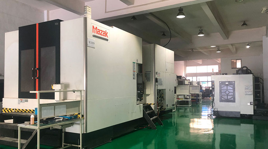 3, 4 and 5-axis precision CNC machining services for aluminum machining, beryllium, carbon steel, magnesium, titanium machining, Inconel, platinum, superalloy, acetal, polycarbonate, fiberglass, graphite and wood. Capable of machining parts up to 98 in. turning dia. and +/-0.001 in. straightness tolerance. Processes include milling, turning, drilling, boring, threading, tapping, forming, knurling, counterboring, countersinking, reaming and laser cutting. Secondary services such as assembly, centerless grinding, heat treating, plating and welding. Prototype and low to high volume production offered with maximum 50,000 units. Suitable for fluid power, pneumatics, hydraulics and valve applications. Serves the aerospace, aircraft, military, medical and defense industries.PTJ will strategize with you to provide the most cost-effective services to help you reach your target,Welcome to Contact us ( [email protected] ) directly for your new project.
- 5 Axis Machining
- Cnc Milling
- Cnc Turning
- Machining Industries
- Machining Process
- Surface Treatment
- Metal Machining
- Plastic Machining
- Powder Metallurgy Mold
- Die Casting
- Parts Gallery
- Auto Metal Parts
- Machinery Parts
- LED Heatsink
- Building Parts
- Mobile Parts
- Medical Parts
- Electronic Parts
- Tailored Machining
- Bicycle Parts
- Aluminum Machining
- Titanium Machining
- Stainless Steel Machining
- Copper Machining
- Brass Machining
- Super Alloy Machining
- Peek Machining
- UHMW Machining
- Unilate Machining
- PA6 Machining
- PPS Machining
- Teflon Machining
- Inconel Machining
- Tool Steel Machining
- More Material

