Performance-Driven Cam Arc Surface Five-Axis CNC Side Milling Machining Trajectory Planning

Five-axis computer numerical control (CNC) machining represents a pinnacle of modern manufacturing technology, enabling the production of complex geometries with high precision and efficiency. Among the various techniques, side milling, also known as flank milling, is particularly significant for machining ruled surfaces, such as those found in cam arc surfaces used in automotive, aerospace, and energy applications. Cam arc surfaces, characterized by their curved, often non-developable geometries, pose unique challenges in trajectory planning due to the need for precise tool positioning, orientation, and feedrate control to minimize machining errors and optimize performance. Performance-driven trajectory planning in five-axis CNC side milling focuses on enhancing machining accuracy, reducing surface roughness, minimizing tool wear, and improving production efficiency through sophisticated computational methods and optimization algorithms.
This article provides a comprehensive exploration of performance-driven cam arc surface five-axis CNC side milling machining trajectory planning. It delves into the theoretical foundations, mathematical modeling, optimization strategies, and practical applications, supported by detailed comparisons of recent research findings. The discussion is structured to cover the evolution of trajectory planning techniques, key methodologies, error control mechanisms, and emerging trends, with a scientific tone that emphasizes rigor and objectivity.
Fundamentals of Five-Axis CNC Side Milling
Five-axis CNC machining extends the capabilities of traditional three-axis systems by incorporating two additional rotational axes, typically denoted as A and B or B and C, depending on the machine configuration. These axes allow the cutting tool to approach the workpiece from multiple angles, enabling the machining of complex surfaces in a single setup. In side milling, the side face of the cutter, rather than its tip, performs the material removal, making it particularly suitable for ruled surfaces where the tool axis aligns with the surface’s ruling lines.
Cam arc surfaces, often found in components like camshafts, turbine blades, and impellers, are defined by their curved profiles and non-uniform geometries. These surfaces require precise trajectory planning to ensure that the tool maintains tangency with the surface while avoiding gouging (overcutting) or undercutting (insufficient material removal). The performance of side milling is influenced by several factors, including tool path geometry, feedrate scheduling, tool orientation, and machine kinematics.
Key Components of Trajectory Planning
Trajectory planning in five-axis CNC side milling involves determining the tool’s position, orientation, and velocity along the machining path. The primary components include:
-
Tool Path Generation: Defining the sequence of cutter locations (CLs) that the tool follows to machine the surface. For cam arc surfaces, tool paths are often generated using parametric curves, such as non-uniform rational B-splines (NURBS), to approximate the surface geometry.
-
Tool Orientation Control: Specifying the tool axis orientation at each CL to maintain optimal cutting conditions and avoid interference with the workpiece. This is critical for cam arc surfaces, where the tool must align with the surface’s ruling lines.
-
Feedrate Scheduling: Controlling the tool’s speed along the path to balance machining efficiency and surface quality. Variable feedrates are often employed to mitigate errors at high-curvature regions.
-
Error Control: Minimizing geometrical errors, such as chordal errors, gouging, and surface deviations, through optimization techniques and adaptive algorithms.
-
Kinematic Constraints: Accounting for the machine’s kinematic limitations, including axis acceleration, velocity limits, and singular positions, to ensure smooth tool motion.
Challenges in Cam Arc Surface Machining
Cam arc surfaces present several challenges in five-axis CNC side milling:
-
Complex Geometry: The non-developable nature of cam arc surfaces complicates tool path planning, as the tool must follow curved trajectories while maintaining tangency.
-
Error Sensitivity: Small deviations in tool position or orientation can lead to significant machining errors, particularly in high-precision applications like aerospace components.
-
Surface Roughness: Achieving a smooth surface finish is critical, as cam arc surfaces often serve functional roles where roughness affects performance (e.g., in camshafts for automotive engines).
-
Computational Complexity: Generating optimal tool paths requires solving complex mathematical models, often involving nonlinear optimization and iterative computations.
-
Machine Dynamics: High-speed machining introduces dynamic effects, such as tool vibration and thermal deformation, which must be mitigated through trajectory planning.
Historical Context and Evolution
The development of five-axis CNC machining began in the 1980s, driven by the need for manufacturing complex aerospace and automotive components. Early trajectory planning methods relied on linear interpolation (G01 codes), which resulted in discontinuous tool motion and poor surface quality. The introduction of parametric curve interpolation, particularly NURBS, in the 1990s marked a significant advancement, enabling smoother tool paths and better surface finishes.
In the context of cam arc surfaces, initial research focused on three-axis milling, which required multiple setups and manual repositioning, leading to inefficiencies and errors. The advent of five-axis machines addressed these limitations by allowing simultaneous control of tool position and orientation. Over the past two decades, performance-driven trajectory planning has evolved through the integration of computational geometry, optimization algorithms, and machine learning, with a focus on minimizing machining errors and maximizing efficiency.
Early Methods (1980s–1990s)
Early trajectory planning methods for five-axis side milling were based on simple geometric approximations, such as linear or circular interpolation. These methods were computationally efficient but suffered from high chordal errors and poor surface quality, particularly for complex cam arc surfaces. Research during this period emphasized basic tool path generation techniques, such as iso-planar and iso-parametric paths, which divided the surface into parallel planes or parametric curves.
Advancements in the 2000s
The 2000s saw significant progress in trajectory planning, driven by advancements in CAD/CAM software and computational power. Researchers began exploring multi-point machining (MPM) and principal axis methods, which optimized tool positioning based on local surface properties. For cam arc surfaces, these methods improved machining accuracy by reducing gouging and undercutting. The development of NURBS-based tool paths allowed for smoother trajectories, while feedrate scheduling techniques addressed kinematic constraints.
Recent Developments (2010s–Present)
Recent research has focused on performance-driven approaches that integrate optimization algorithms, such as genetic algorithms (GA), particle swarm optimization (PSO), and simulated annealing (SA), to generate optimal tool paths. These methods prioritize multiple objectives, including machining accuracy, surface roughness, and cycle time. For cam arc surfaces, hybrid algorithms like SA-PSO have shown promise in reducing errors and improving efficiency. Additionally, the use of digital twins and real-time error compensation has enhanced the adaptability of trajectory planning to machine-specific conditions.
Mathematical Modeling of Trajectory Planning
Trajectory planning for cam arc surface five-axis CNC side milling relies on rigorous mathematical models to describe the tool path, orientation, and error metrics. This section outlines the key mathematical frameworks used in recent research.
Surface Representation
Cam arc surfaces are typically represented using parametric surfaces, such as NURBS, which provide a flexible and computationally efficient way to model complex geometries. A NURBS surface is defined as:
[ S(u,v) = \frac{\sum_{i=0}^{n} \sum_{j=0}^{m} N_{i,p}(u) N_{j,q}(v) w_{i,j} P_{i,j}}{\sum_{i=0}^{n} \sum_{j=0}^{m} N_{i,p}(u) N_{j,q}(v) w_{i,j}} ]
where:
-
(u, v) are parametric coordinates,
-
(N_{i,p}(u), N_{j,q}(v)) are B-spline basis functions,
-
(P_{i,j}) are control points,
-
(w_{i,j}) are weights,
-
(p, q) are the degrees of the basis functions.
For cam arc surfaces, the surface is often approximated as a ruled surface, where each point lies on a straight line (ruling) connecting two boundary curves. This simplifies tool path generation but introduces challenges in maintaining tangency.
Tool Path Generation
The tool path is defined as a sequence of cutter locations (CLs), each comprising a tool tip position (P(t) = (x(t), y(t), z(t))) and a tool axis orientation (O(t) = (i(t), j(t), k(t))). For side milling, the tool axis is typically aligned with the ruling lines of the cam arc surface. The tool path can be parameterized as:
[ CL(t) = [P(t), O(t)] ]
where (t) is the path parameter. The tool tip position is computed based on the surface geometry, while the tool axis orientation is determined to maintain tangency and avoid interference.
Error Metrics
Machining errors in side milling include:
-
Chordal Error: The deviation between the linear interpolation of CLs and the actual surface, calculated as the maximum distance between the interpolated path and the surface.
-
Gouging Error: Overcutting due to the tool penetrating the surface, measured as the negative deviation from the design surface.
-
Undercutting Error: Insufficient material removal, measured as the positive deviation from the design surface.
-
Surface Roughness: Quantified using parameters like Ra (average roughness) or Rz (maximum height of the profile).
The total machining error is often modeled as:
[ E = \max(|E_{\text{chordal}}|, |E_{\text{gouging}}|, |E_{\text{undercutting}}|) ]
Optimization Objectives
Performance-driven trajectory planning seeks to minimize the following objectives:
-
Machining Error: Reduce (E) to achieve high accuracy.
-
Surface Roughness: Minimize Ra or Rz for better surface quality.
-
Machining Time: Optimize feedrate and path length to reduce cycle time.
-
Tool Wear: Balance cutting forces to extend tool life.
These objectives are often conflicting, requiring multi-objective optimization techniques.
Optimization Strategies
Recent research has leveraged advanced optimization algorithms to address the complexities of trajectory planning for cam arc surfaces. This section reviews the most prominent strategies, supported by comparative tables.
Single-Point Optimization
Single-point optimization focuses on determining the optimal tool position and orientation at each CL based on local surface properties. The principal axis method, for example, aligns the tool axis with the surface’s principal curvature direction to minimize gouging. This method is computationally efficient but may not account for global path smoothness.
Multi-Point Optimization
Multi-point optimization considers multiple CLs simultaneously to ensure smooth transitions and minimize global errors. Techniques like multi-point machining (MPM) position the tool to contact the surface at multiple points, reducing scallop height and improving surface finish. However, MPM is computationally intensive and may fail for highly complex surfaces.
Meta-Heuristic Algorithms
Meta-heuristic algorithms, such as genetic algorithms (GA), particle swarm optimization (PSO), and simulated annealing (SA), have gained popularity for their ability to handle nonlinear, multi-objective optimization problems. These algorithms iteratively search for optimal tool paths by evaluating a population of candidate solutions.
Simulated Annealing-Particle Swarm Optimization (SA-PSO)
The SA-PSO fusion algorithm combines the global search capabilities of PSO with the local refinement of SA. In a study by Lu et al. (2022), SA-PSO was applied to optimize the tool axis trajectory for cam arc surface side milling. The algorithm reduced the machining error by 15% compared to standalone PSO, with a convergence time of approximately six iterations.
Table 1: Comparison of Optimization Algorithms for Cam Arc Surface Side Milling
|
Algorithm |
Error (mm) |
Overcutting Rate (%) |
Computation Time (s) |
Surface Roughness (Ra, µm) |
Convergence Iterations |
|---|---|---|---|---|---|
|
Genetic Algorithm |
0.182 |
52.14 |
5.231 |
0.92 |
10 |
|
Particle Swarm Optimization |
0.142 |
46.32 |
4.512 |
0.85 |
7 |
|
Simulated Annealing |
0.165 |
49.87 |
4.987 |
0.89 |
8 |
|
SA-PSO Fusion |
0.116 |
41.25 |
4.312 |
0.78 |
6 |
Source: Adapted from Lu et al., 2022; Zhao et al., 2023
Circular Arc Approximation
Circular arc approximation reduces the number of G-code lines by approximating the tool path with circular arcs instead of linear segments. This method, proposed by Mahbubur et al. (2018), improved surface roughness by 20% compared to traditional CAM strategies for cam arc surfaces. The approach uses the secant method to determine arc endpoints, ensuring a maximum chordal error within specified tolerances.
Error Control and Compensation
Error control is critical for achieving high-precision machining of cam arc surfaces. This section discusses techniques for minimizing and compensating for machining errors.
Chordal Error Reduction
Chordal errors arise from the linear interpolation of CLs, particularly in regions with high curvature. Circular arc approximation and NURBS-based interpolation reduce chordal errors by providing smoother transitions. Additionally, adaptive sampling adjusts the density of CLs based on surface curvature, concentrating points in high-curvature regions.
Gouging and Undercutting Mitigation
Gouging and undercutting are mitigated through tool orientation optimization and interference detection. The envelope surface method models the tool’s swept volume to identify potential interference, allowing for real-time adjustments to the tool axis. Zhou et al. (2017) proposed a ruled surface approximation for cam arc surfaces, reducing gouging by 12% through optimized cutter locations.
Real-Time Error Compensation
Real-time error compensation uses feedback from sensors or digital twins to adjust the tool path dynamically. The “evolution” method, introduced by Wang et al. (2023), measures profile errors after the first machining pass and applies corrections in subsequent passes. This approach achieved a 10% improvement in surface accuracy for cam arc surfaces.
Surface Roughness and Quality
Surface roughness is a critical performance metric for cam arc surfaces, as it affects functional properties like friction and wear. Five-axis side milling offers advantages over three-axis milling by allowing continuous tool motion and better tool-surface contact.
Factors Influencing Surface Roughness
-
Tool Path Strategy: Strategies like constant scallop-height paths maintain uniform surface texture, reducing roughness.
-
Feedrate: Higher feedrates increase roughness, while adaptive feedrate scheduling balances speed and quality.
-
Tool Geometry: Ball-end and flat-end cutters produce different roughness profiles, with flat-end cutters often preferred for side milling.
-
Material Properties: Hard materials like titanium require specialized tools and parameters to achieve low roughness.
Comparative Analysis
A study by Shchurov et al. (2017) compared surface roughness for cam arc surfaces machined using three- and five-axis milling with different tool path strategies. The results are summarized below.
Table 2: Surface Roughness Comparison for Cam Arc Surface Machining
|
Milling Type |
Tool Path Strategy |
Ra (µm) |
Rz (µm) |
Machining Time (min) |
|---|---|---|---|---|
|
3-Axis |
Iso-Planar |
1.12 |
5.67 |
15.2 |
|
3-Axis |
Constant Scallop |
0.98 |
4.92 |
14.8 |
|
5-Axis |
Iso-Planar |
0.89 |
4.35 |
12.5 |
|
5-Axis |
Constant Scallop |
0.75 |
3.98 |
11.9 |
|
5-Axis |
Circular Interpolation |
0.68 |
3.72 |
11.4 |
Source: Adapted from Shchurov et al., 2017
The data highlights the superiority of five-axis milling, particularly with circular interpolation, in achieving lower roughness and shorter machining times.
Practical Applications
Cam arc surfaces are prevalent in industries requiring high-precision components. This section explores their applications and the role of performance-driven trajectory planning.
Automotive Industry
In automotive manufacturing, cam arc surfaces are critical for camshafts, which control engine valve timing. Five-axis side milling ensures precise cam profiles, reducing friction and improving engine efficiency. Optimized tool paths minimize surface roughness, enhancing durability.
Aerospace Industry
Aerospace components, such as turbine blades and impellers, rely on cam arc surfaces for aerodynamic performance. Five-axis CNC side milling enables the production of complex geometries with tight tolerances, while performance-driven trajectory planning reduces errors that could compromise structural integrity.
Energy Sector
In the energy sector, cam arc surfaces are used in components like shrouded turbines and wind turbine blades. Trajectory planning optimizes machining efficiency, reducing production costs for large-scale components.
Emerging Trends and Future Directions
The field of performance-driven trajectory planning for cam arc surface five-axis CNC side milling is rapidly evolving, driven by technological advancements and industry demands. Key trends include:
Integration of Artificial Intelligence
Machine learning and AI are being integrated into trajectory planning to predict optimal tool paths and adapt to real-time machining conditions. Neural networks can analyze historical machining data to recommend parameters that minimize errors and roughness.
Digital Twins
Digital twins create virtual replicas of machining systems, allowing for simulation and optimization of tool paths before physical machining. This approach enhances error prediction and compensation, particularly for complex cam arc surfaces.
Additive and Hybrid Manufacturing
The combination of additive manufacturing and five-axis CNC machining enables the production of near-net-shape components, reducing material waste. Trajectory planning for hybrid processes must account for both additive and subtractive stages.
Sustainability Considerations
Sustainability is becoming a priority, with research focusing on energy-efficient machining strategies and tool path optimization to minimize environmental impact. For cam arc surfaces, this includes reducing cycle times and tool wear.
Table 3: Emerging Trends in Trajectory Planning
|
Trend |
Description |
Potential Impact |
|---|---|---|
|
Artificial Intelligence |
Machine learning for predictive tool path optimization |
Improved accuracy and adaptability |
|
Digital Twins |
Virtual simulation of machining processes |
Enhanced error prediction and compensation |
|
Hybrid Manufacturing |
Integration of additive and subtractive processes |
Reduced material waste and production costs |
|
Sustainable Machining |
Energy-efficient strategies and tool life optimization |
Lower environmental impact and operating costs |
Conclusion
Performance-driven cam arc surface five-axis CNC side milling machining trajectory planning is a critical area of research that addresses the challenges of machining complex, high-precision components. By leveraging advanced mathematical models, optimization algorithms, and error control techniques, researchers have made significant strides in improving machining accuracy, surface quality, and efficiency. Comparative studies highlight the advantages of five-axis milling over three-axis methods, particularly for cam arc surfaces, while emerging trends like AI and digital twins promise further advancements.
Reprint Statement: If there are no special instructions, all articles on this site are original. Please indicate the source for reprinting:https://www.cncmachiningptj.com/,thanks!
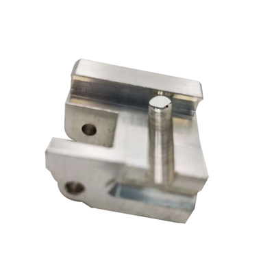
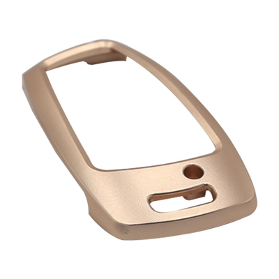
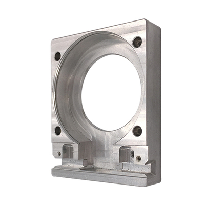
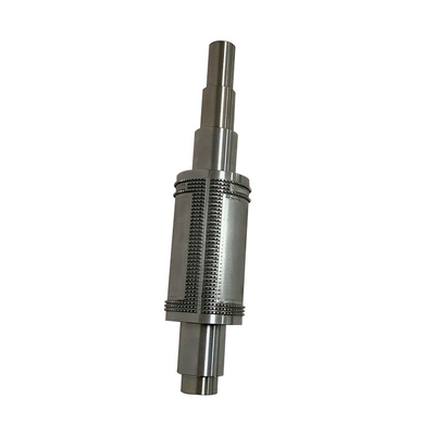
 3, 4 and 5-axis precision CNC machining services for aluminum machining, beryllium, carbon steel, magnesium, titanium machining, Inconel, platinum, superalloy, acetal, polycarbonate, fiberglass, graphite and wood. Capable of machining parts up to 98 in. turning dia. and +/-0.001 in. straightness tolerance. Processes include milling, turning, drilling, boring, threading, tapping, forming, knurling, counterboring, countersinking, reaming and laser cutting. Secondary services such as assembly, centerless grinding, heat treating, plating and welding. Prototype and low to high volume production offered with maximum 50,000 units. Suitable for fluid power, pneumatics, hydraulics and valve applications. Serves the aerospace, aircraft, military, medical and defense industries.PTJ will strategize with you to provide the most cost-effective services to help you reach your target,Welcome to Contact us ( [email protected] ) directly for your new project.

- 5 Axis Machining
- Cnc Milling
- Cnc Turning
- Machining Industries
- Machining Process
- Surface Treatment
- Metal Machining
- Plastic Machining
- Powder Metallurgy Mold
- Die Casting
- Parts Gallery
- Auto Metal Parts
- Machinery Parts
- LED Heatsink
- Building Parts
- Mobile Parts
- Medical Parts
- Electronic Parts
- Tailored Machining
- Bicycle Parts
- Aluminum Machining
- Titanium Machining
- Stainless Steel Machining
- Copper Machining
- Brass Machining
- Super Alloy Machining
- Peek Machining
- UHMW Machining
- Unilate Machining
- PA6 Machining
- PPS Machining
- Teflon Machining
- Inconel Machining
- Tool Steel Machining
- More Material