Research and Flight Test Verification of Full Authority Numerical Control Systems for Aircraft Engines
The advent of digital technology in aviation has revolutionized aircraft engine management, with the Full Authority Digital Engine Control (FADEC) system representing a pinnacle of this transformation. FADEC is a sophisticated system comprising a digital computer, known as the Electronic Engine Controller (EEC) or Engine Control Unit (ECU), and associated accessories that govern all aspects of aircraft engine performance. Unlike traditional mechanical or hydromechanical control systems, FADEC exercises complete authority over engine parameters without manual override, optimizing efficiency, safety, and performance across diverse flight conditions. This article delves into the research, development, and flight test verification processes that have shaped FADEC systems, exploring their technological evolution, testing methodologies, and impact on modern aviation.
FADEC systems emerged in response to the increasing complexity of aircraft engines and the demand for precise control to enhance fuel efficiency, reduce emissions, and improve reliability. By integrating multiple input variables—such as air density, throttle position, engine temperatures, and pressures—FADEC processes data in real time, adjusting parameters like fuel flow, stator vane position, and bleed valve settings up to 70 times per second. This capability ensures optimal engine operation, minimizes pilot workload, and enables manufacturers to program specific limitations, such as temperature thresholds, to prevent engine damage. The absence of manual override distinguishes true FADEC from partial digital controls, placing full trust in the system’s computational capabilities, though this also introduces unique challenges, such as the risk of total engine failure in the event of a FADEC malfunction.
The development of FADEC systems has been a collaborative effort involving aerospace manufacturers, research institutions, and regulatory bodies. Early experiments in the 1960s and 1970s, such as those by Rolls-Royce and NASA, laid the groundwork for digital engine control, with subsequent decades witnessing refinements in hardware, software, and testing protocols. Flight test verification, a critical phase in FADEC development, ensures that these systems perform reliably under real-world conditions, meeting stringent safety and performance standards set by authorities like the Federal Aviation Administration (FAA) and the European Union Aviation Safety Agency (EASA). This article provides a comprehensive examination of FADEC research and flight testing, structured into distinct sections to address historical context, technical design, testing methodologies, case studies, and future directions.
Historical Context and Evolution of Engine Control Systems
The evolution of aircraft engine control systems reflects broader advancements in aerospace engineering and computing technology. In the early days of aviation, engine controls were purely mechanical, relying on physical linkages manipulated by pilots to adjust fuel flow and power output. For example, the Kommandogerät, a mechanical-hydraulic control unit developed for Germany’s BMW 801 radial engine during World War II, represented an early attempt to streamline engine management. These systems, while effective for their time, were limited by their inability to adapt dynamically to changing flight conditions and required significant pilot input.
The transition to electronic control began in the 1960s with analogue systems, which varied electrical signals to communicate engine settings. Rolls-Royce and Snecma introduced analogue controls in the Olympus 593 engine for the Concorde, marking a significant step forward. However, analogue systems suffered from electronic noise and reliability issues, prompting the development of digital controls. In 1968, Rolls-Royce and Elliott Automation collaborated on a digital engine control system for the Rolls-Royce Olympus Mk 320, which completed hundreds of hours of operation. Concurrently, NASA and Pratt & Whitney tested an experimental FADEC on an F-111 aircraft equipped with a modified Pratt & Whitney TF30 engine, demonstrating the feasibility of digital control in flight.
By the 1980s, FADEC systems had matured, incorporating redundant digital channels to enhance safety and fault tolerance. These systems were adopted in both piston and jet engines, with manufacturers like General Electric and Pratt & Whitney integrating FADEC into commercial and military aircraft. The absence of manual override in true FADEC systems necessitated rigorous testing to ensure reliability, as a total failure could result in engine shutdown. Redundancy, typically in the form of dual or triple digital channels, mitigated this risk, allowing each channel to independently manage engine functions. The evolution of FADEC has been driven by advances in microprocessors, sensors, and software, enabling increasingly sophisticated control algorithms and real-time data processing.
Technical Design of FADEC Systems
Core Components and Architecture
A FADEC system is a complex assembly of hardware and software designed to optimize engine performance. The core component is the EEC or ECU, a digital computer that processes input data and issues control commands. The EEC interfaces with a network of sensors and actuators, which monitor and adjust engine parameters. Key components include:
-
Electronic Engine Controller (EEC): The central processing unit, typically a ruggedized computer capable of operating in extreme environments. The EEC runs control algorithms, processes sensor data, and communicates with the aircraft’s avionics systems.
-
Sensors: These measure variables such as air temperature, pressure, throttle position, engine speed, and exhaust gas temperature. Modern FADEC systems may incorporate up to 100 sensors, providing a comprehensive dataset for control decisions.
-
Actuators: Electromechanical devices that adjust engine components, such as fuel valves, variable stator vanes, and bleed valves, based on EEC commands.
-
Redundant Channels: Dual or triple digital channels ensure fault tolerance, with each channel capable of independently controlling the engine. Redundancy mitigates the risk of single-point failures.
-
Power Supply: A dedicated power source, often backed by the aircraft’s electrical system, ensures continuous operation of the FADEC.
The architecture of a FADEC system is designed for high reliability and real-time performance. The EEC typically employs a real-time operating system (RTOS) to manage tasks, ensuring that control commands are executed within milliseconds. Communication with the aircraft’s flight management system (FMS) allows FADEC to integrate flight data, such as wind conditions and cruise altitude, into its control strategy.
Control Algorithms and Software
FADEC’s control algorithms are the heart of its functionality, enabling precise management of engine parameters. These algorithms are developed using mathematical models of engine behavior, which account for thermodynamic, aerodynamic, and mechanical properties. Common control strategies include:
-
Proportional-Integral-Derivative (PID) Control: Used to regulate variables like fuel flow by minimizing the error between desired and actual values.
-
Model-Based Control: Incorporates real-time engine models to predict performance and adjust parameters proactively.
-
Fault-Tolerant Control: Detects and compensates for sensor or actuator failures, ensuring continued operation within safety limits.
Software development for FADEC systems adheres to stringent standards, such as DO-178C, which governs airborne software certification. The software undergoes extensive verification and validation to ensure correctness and reliability. Automated code generation tools, such as those based on MATLAB/Simulink, are often used to translate control models into executable code, reducing development time and errors.
Input Variables and Processing
FADEC systems process a wide range of input variables, which are analyzed up to 70 times per second to compute optimal engine settings. Table 1 provides a detailed comparison of input variables across different FADEC generations.
Table 1: Comparison of FADEC Input Variables Across Generations
|
Generation |
Year Introduced |
Number of Input Variables |
Key Variables |
Processing Frequency (Hz) |
Applications |
|---|---|---|---|---|---|
|
1st (1970s) |
1975 |
~20 |
Throttle position, engine speed, exhaust temperature |
10-20 |
Experimental (e.g., F-111) |
|
2nd (1980s) |
1985 |
~50 |
Air density, pressure, temperature, fuel flow |
20-50 |
Commercial jets (e.g., Boeing 737) |
|
3rd (1990s) |
1995 |
~80 |
Stator vane position, bleed valve status, vibration |
50-70 |
Military fighters (e.g., F-22) |
|
4th (2000s) |
2005 |
~100 |
Environmental conditions, aircraft altitude, health monitoring |
70 |
Modern airliners (e.g., Boeing 787) |
The increase in input variables reflects advancements in sensor technology and computing power, enabling more granular control and diagnostic capabilities. For example, modern FADEC systems monitor vibration patterns to detect potential mechanical issues, providing maintenance alerts to ground crews.
Research and Development Processes
Theoretical Modeling and Simulation
The development of FADEC systems begins with theoretical modeling, which establishes the mathematical framework for engine control. Engineers use computational fluid dynamics (CFD), finite element analysis (FEA), and thermodynamic models to simulate engine behavior under various conditions. These models are implemented in simulation environments, such as MATLAB/Simulink or proprietary software, to test control algorithms before hardware integration.
Simulation plays a critical role in identifying potential issues, such as control instability or sensor drift, early in the development process. Hardware-in-the-loop (HIL) testing integrates physical EEC hardware with simulated engine models, allowing engineers to evaluate system performance in a controlled environment. HIL testing reduces the need for costly engine test runs and enables rapid iteration of control algorithms.
Laboratory Testing
Laboratory testing validates FADEC components under controlled conditions. Test benches, equipped with real or simulated engine hardware, replicate flight environments, including temperature extremes, vibration, and electromagnetic interference. Key tests include:
-
Environmental Testing: Assesses the EEC’s performance in high-temperature, low-pressure, or humid conditions, simulating high-altitude flight.
-
Endurance Testing: Subjects the FADEC to prolonged operation to evaluate reliability and wear.
-
Fault Injection Testing: Introduces simulated failures, such as sensor malfunctions, to verify fault-tolerant control strategies.
Table 2 compares laboratory testing protocols for FADEC systems across major manufacturers.
Table 2: Comparison of FADEC Laboratory Testing Protocols
|
Manufacturer |
Test Bench Type |
Environmental Conditions Tested |
Endurance Test Duration (Hours) |
Fault Injection Scenarios |
Certification Standard |
|---|---|---|---|---|---|
|
General Electric |
Real engine |
-50°C to 85°C, 0.1-1 atm |
5,000 |
Sensor failure, actuator jam |
DO-178C, ARP4754A |
|
Pratt & Whitney |
Simulated engine |
-40°C to 90°C, 0.2-1.2 atm |
4,000 |
Power loss, communication error |
DO-178C, ARP4754A |
|
Rolls-Royce |
Hybrid (real/simulated) |
-60°C to 100°C, 0.05-1.5 atm |
6,000 |
Software crash, redundant channel failure |
DO-178C, ARP4754A |
|
Collins Aerospace |
Simulated engine |
-55°C to 80°C, 0.1-1 atm |
4,500 |
Multiple simultaneous failures |
DO-178C, ARP4754A |
Laboratory testing ensures that FADEC systems meet regulatory requirements before proceeding to flight testing, reducing the risk of in-flight failures.
Flight Test Verification Methodologies
Objectives and Scope
Flight test verification is the final stage in FADEC development, confirming that the system performs as intended under real-world conditions. The primary objectives are to validate control accuracy, assess reliability, and ensure compliance with airworthiness standards. Flight tests are conducted on testbed aircraft, such as modified commercial jets or dedicated research platforms, equipped with instrumentation to monitor FADEC performance.
The scope of flight testing encompasses various flight phases, including takeoff, cruise, landing, and emergency scenarios. Tests evaluate FADEC’s response to dynamic conditions, such as turbulence, altitude changes, and engine transients. Regulatory bodies, such as the FAA and EASA, mandate specific test scenarios to demonstrate compliance with safety and performance criteria.
Testbed Aircraft and Instrumentation
Testbed aircraft are critical to FADEC flight testing, providing a platform to evaluate system performance in realistic environments. Common testbeds include:
-
Boeing 737 (NASA TCV Program): Used for digital control research, equipped with advanced avionics and data acquisition systems.
-
F/A-18 (NASA LVAC Experiment): Employed to simulate heavy-lift vehicle dynamics, testing FADEC algorithms in high-performance scenarios.
-
Cessna 525B: Utilized for business jet FADEC testing, particularly for active winglet integration.
Instrumentation includes high-frequency data recorders, pressure transducers, thermocouples, and vibration sensors, which capture real-time engine and FADEC data. Redundant data acquisition systems ensure reliability, with some testbeds incorporating telemetry for real-time ground monitoring.
Test Scenarios and Procedures
Flight test scenarios are designed to stress FADEC systems across their operational envelope. Key scenarios include:
-
Startup and Shutdown: Verifies FADEC’s control of engine ignition and shutdown, critical for reliability.
-
Thrust Transients: Tests rapid changes in throttle settings to assess control stability and response time.
-
High-Altitude Operation: Evaluates performance at low pressure and temperature, simulating cruise conditions.
-
Emergency Scenarios: Simulates sensor failures or power losses to validate fault-tolerant control.
-
Environmental Extremes: Assesses FADEC performance in icing, high humidity, or extreme heat.
Procedures follow a structured methodology, beginning with ground tests to confirm system readiness, followed by low-risk flight profiles and progressing to high-stress scenarios. Test pilots and engineers collaborate to monitor real-time data, adjusting test parameters as needed.
Case Study: NASA’s TCV Program
NASA’s Terminal Configured Vehicle (TCV) program, conducted in the 1970s and 1980s, utilized a modified Boeing 737 to research digital engine controls. The program developed automated testing techniques, including software generation and validation systems, to streamline FADEC verification. Flight tests demonstrated the feasibility of digital navigation, guidance, and engine control, paving the way for modern FADEC systems. The TCV program’s emphasis on cost reduction and automation influenced subsequent testing methodologies, highlighting the importance of integrated test environments.
Case Study: DGEN 380 EECU Testing
A 2021 study published by MDPI detailed the flight test verification of an EECU for the DGEN 380 turbofan engine. Researchers developed a real-time engine model and test bench to simulate startup phase control logic, followed by flight tests to validate performance. The EECU successfully managed engine parameters under dynamic conditions, demonstrating the efficacy of model-based testing and real-time simulation. This case study underscores the role of integrated test environments in bridging laboratory and flight testing.
Challenges and Solutions in FADEC Flight Testing
Technical Challenges
Flight testing FADEC systems presents several challenges, including:
-
System Complexity: The integration of numerous sensors, actuators, and software components increases the risk of unforeseen interactions.
-
Environmental Variability: Real-world conditions, such as turbulence or icing, are difficult to replicate in simulations, requiring robust test designs.
-
Single-Point Failure Risk: The absence of manual override in true FADEC systems necessitates rigorous validation of redundancy mechanisms.
-
Data Overload: High-frequency data acquisition generates vast datasets, complicating real-time analysis and post-test evaluation.
Mitigation Strategies
To address these challenges, engineers employ several strategies:
-
Redundancy Design: Dual or triple digital channels ensure continued operation in the event of a failure, with each channel independently verified during testing.
-
Advanced Simulation: High-fidelity models and HIL testing reduce the reliance on flight tests, allowing engineers to address issues early in development.
-
Automated Data Analysis: Machine learning and data analytics tools process large datasets, identifying anomalies and trends efficiently.
-
Incremental Testing: Progressive test profiles, starting with low-risk scenarios, build confidence in system performance before tackling extreme conditions.
Regulatory and Certification Considerations
Airworthiness Standards
FADEC systems must comply with airworthiness standards set by regulatory bodies, such as FAA’s FAR Part 33 and EASA’s CS-E. These standards mandate rigorous testing to demonstrate safety, reliability, and performance. Key requirements include:
-
Fault Tolerance: The system must maintain safe operation despite single-point failures.
-
Environmental Resilience: Performance must be validated across the operational envelope, including extreme temperatures and pressures.
-
Software Integrity: Software must meet DO-178C Level A standards, ensuring no critical errors.
Certification involves submitting detailed test reports, including flight test data, to regulatory authorities. Independent audits and witness testing by regulators ensure compliance.
Certification Process
The certification process for FADEC systems is multi-phased:
-
Design Approval: Regulators review the system’s design, including hardware, software, and redundancy mechanisms.
-
Ground Testing: Laboratory and ground tests validate component performance and integration.
-
Flight Testing: Flight tests demonstrate real-world performance, with regulators often observing critical tests.
-
Documentation: Comprehensive reports, including test data and analysis, are submitted for review.
-
Type Certification: Upon successful review, the FADEC system is certified for use in specific engine models.
Table 3 outlines the certification timelines for notable FADEC systems.
Table 3: Certification Timelines for FADEC Systems
|
Engine Model |
Manufacturer |
FADEC Introduction Year |
Certification Duration (Months) |
Regulatory Body |
Key Challenges |
|---|---|---|---|---|---|
|
GE90 |
General Electric |
1995 |
24 |
FAA, EASA |
Software validation, redundancy |
|
Trent 800 |
Rolls-Royce |
1996 |
22 |
EASA, FAA |
High-altitude performance |
|
PW4000 |
Pratt & Whitney |
1987 |
20 |
FAA |
Early digital integration |
|
CFM56-7B |
CFM International |
1994 |
18 |
FAA, EASA |
Environmental testing |
Impact on Aviation
Operational Benefits
FADEC systems have transformed aircraft operations by:
-
Enhancing Efficiency: Real-time optimization of fuel flow and engine settings reduces fuel consumption and emissions.
-
Reducing Pilot Workload: Automated control minimizes the need for manual adjustments, allowing pilots to focus on navigation and safety.
-
Improving Reliability: Health monitoring and fault-tolerant designs extend engine service life and reduce maintenance costs.
-
Enabling Flexibility: FADEC’s programmability allows a single engine type to serve multiple thrust requirements, simplifying fleet management.
Environmental Impact
By optimizing fuel combustion, FADEC systems contribute to lower carbon dioxide and particulate matter emissions, aligning with International Civil Aviation Organization (ICAO) standards. For example, the EPA’s 2022 regulations on aircraft engine emissions, which adopted ICAO’s particulate matter standards, were facilitated by FADEC’s precise control capabilities.
Safety Enhancements
The fault-tolerant design of FADEC systems enhances safety by mitigating the impact of component failures. Redundant channels and automated diagnostics ensure that engines remain operational even in adverse conditions, reducing the risk of in-flight shutdowns.
Future Directions
Integration with Advanced Technologies
The future of FADEC systems lies in their integration with emerging technologies, such as:
-
Artificial Intelligence (AI): AI-driven control algorithms can adapt to unforeseen conditions, enhancing fault tolerance and efficiency.
-
Hybrid-Electric Propulsion: FADEC systems are being adapted for hybrid-electric engines, managing complex power distribution between electric and combustion systems.
-
Quantum Computing: Research into quantum computing for FADEC applications promises faster data processing and more sophisticated control models.
Autonomous Aircraft
As autonomous aircraft gain traction, FADEC systems will play a central role in managing propulsion without human intervention. Flight testing of FADEC in unmanned aerial vehicles (UAVs) is already underway, with programs like NASA’s SBIR exploring control-oriented applications.
Sustainability Initiatives
FADEC systems will support aviation’s sustainability goals by enabling alternative fuels and optimizing engine performance for reduced environmental impact. Research into sustainable aviation fuels (SAF) relies on FADEC’s ability to adapt control parameters to new fuel properties.
Conclusion
The research and flight test verification of Full Authority Digital Engine Control systems represent a cornerstone of modern aerospace engineering. From their origins in the 1960s to their widespread adoption in commercial and military aircraft, FADEC systems have redefined engine management, delivering unparalleled efficiency, safety, and reliability. Through rigorous theoretical modeling, laboratory testing, and flight test verification, engineers have overcome technical challenges to ensure that FADEC systems meet the demands of real-world operation. As aviation evolves toward autonomy and sustainability, FADEC systems will continue to drive innovation, shaping the future of flight.
This comprehensive exploration, spanning historical context, technical design, testing methodologies, case studies, and future prospects, underscores the critical role of FADEC in aviation. The detailed tables and structured sections provide a scientific framework for understanding the complexities of FADEC development, offering valuable insights for researchers, engineers, and policymakers alike.
Reprint Statement: If there are no special instructions, all articles on this site are original. Please indicate the source for reprinting:https://www.cncmachiningptj.com/,thanks!
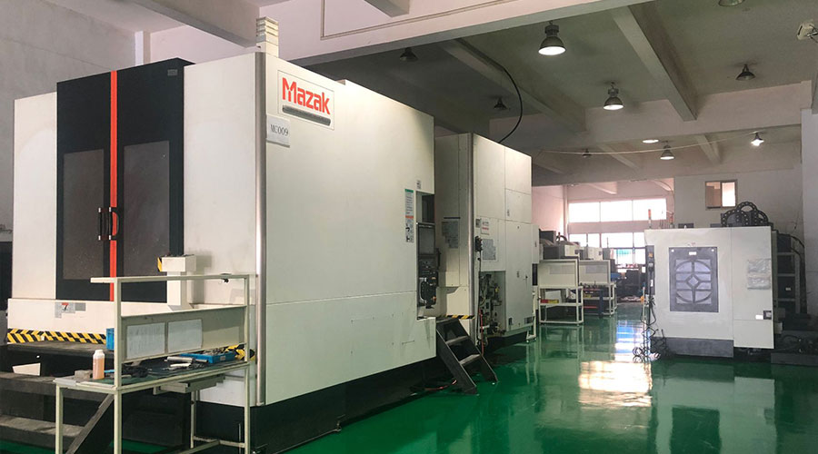 3, 4 and 5-axis precision CNC machining services for aluminum machining, beryllium, carbon steel, magnesium, titanium machining, Inconel, platinum, superalloy, acetal, polycarbonate, fiberglass, graphite and wood. Capable of machining parts up to 98 in. turning dia. and +/-0.001 in. straightness tolerance. Processes include milling, turning, drilling, boring, threading, tapping, forming, knurling, counterboring, countersinking, reaming and laser cutting. Secondary services such as assembly, centerless grinding, heat treating, plating and welding. Prototype and low to high volume production offered with maximum 50,000 units. Suitable for fluid power, pneumatics, hydraulics and valve applications. Serves the aerospace, aircraft, military, medical and defense industries.PTJ will strategize with you to provide the most cost-effective services to help you reach your target,Welcome to Contact us ( [email protected] ) directly for your new project.

- 5 Axis Machining
- Cnc Milling
- Cnc Turning
- Machining Industries
- Machining Process
- Surface Treatment
- Metal Machining
- Plastic Machining
- Powder Metallurgy Mold
- Die Casting
- Parts Gallery
- Auto Metal Parts
- Machinery Parts
- LED Heatsink
- Building Parts
- Mobile Parts
- Medical Parts
- Electronic Parts
- Tailored Machining
- Bicycle Parts
- Aluminum Machining
- Titanium Machining
- Stainless Steel Machining
- Copper Machining
- Brass Machining
- Super Alloy Machining
- Peek Machining
- UHMW Machining
- Unilate Machining
- PA6 Machining
- PPS Machining
- Teflon Machining
- Inconel Machining
- Tool Steel Machining
- More Material

