CNC Machining of Cylindrical Indexing Cam
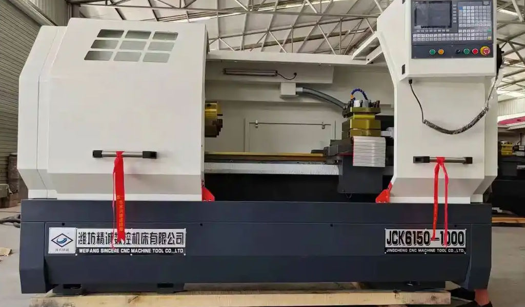
CNC (Computer Numerical Control) machining is a pivotal manufacturing process in modern industry, enabling the precise fabrication of complex components such as cylindrical indexing cams. These mechanical elements are critical in automated machinery, particularly in applications requiring precise intermittent motion, such as tool changers in machining centers, assembly lines, and packaging equipment. This article provides an exhaustive exploration of the design, analysis, and CNC machining of cylindrical indexing cams, delving into their theoretical foundations, practical implementation, and technological advancements. The discussion is structured to cover historical context, kinematic principles, design methodologies, machining processes, material considerations, software integration, optimization strategies, and future trends, ensuring a comprehensive understanding of this specialized field.
Historical Context and Evolution
The development of cylindrical indexing cams is rooted in the broader history of cam mechanisms, which have been integral to mechanical engineering since the Industrial Revolution. Early cams, used in textile machinery and steam engines, were simple planar or disc-shaped components designed to convert rotary motion into linear or oscillatory motion. The advent of cylindrical indexing cams in the 20th century marked a significant advancement, enabling more complex motion profiles in automated systems. These cams, characterized by their cylindrical geometry and ability to index a follower to precise angular positions, became essential in high-speed, high-precision applications.
The introduction of CNC machining in the 1960s revolutionized cam manufacturing. Prior to CNC, cam profiles were crafted using manual milling or copying from master cams, processes that were time-consuming and prone to errors. CNC technology, with its ability to execute complex toolpaths based on digital instructions, allowed for the precise machining of intricate cam surfaces. The integration of Computer-Aided Design (CAD) and Computer-Aided Manufacturing (CAM) software further enhanced design accuracy and manufacturing efficiency, enabling engineers to model and simulate cam behavior before production.
By the 1980s, CNC machining of cylindrical indexing cams had become a standard practice in industries such as automotive, aerospace, and robotics. Advances in multi-axis CNC machines, particularly 4- and 5-axis systems, facilitated the production of cams with complex spatial geometries. Today, cylindrical indexing cams are designed and machined with unprecedented precision, driven by advancements in control systems, cutting tools, and simulation software.
Fundamental Principles of Cylindrical Indexing Cams
Definition and Function
A cylindrical indexing cam is a mechanical component with a cylindrical surface that features a contoured groove or ridge. This contour engages a follower, typically a roller or pin, to produce intermittent rotary or linear motion. The cam's primary function is to index a follower to specific angular positions, ensuring precise positioning in automated machinery. Unlike continuous-motion cams, indexing cams produce discrete motion, making them ideal for applications requiring stop-and-go sequences, such as tool magazines in CNC machining centers.
Kinematic Characteristics
The kinematic behavior of a cylindrical indexing cam is governed by its geometry and the motion profile imparted to the follower. The cam's cylindrical surface is defined by a coordinate system where the axial direction (z-axis) corresponds to the cam's length, and the angular direction (θ) corresponds to its rotation. The follower's motion is determined by the cam's contour, which is designed to achieve specific displacement, velocity, and acceleration profiles.
The displacement function, s(θ), describes the follower's position as a function of the cam's angular position. Common motion laws include modified trapezoidal, cycloidal, and polynomial profiles, each selected based on the application's requirements for smoothness and dynamic performance. The velocity and acceleration of the follower are derived as:
-
Velocity: v(θ) = ds/dθ · dθ/dt
-
Acceleration: a(θ) = d²s/dθ² · (dθ/dt)² + ds/dθ · d²θ/dt²
These equations highlight the importance of controlling the cam's rotational speed (dθ/dt) and ensuring smooth derivatives to minimize jerk, which can cause vibrations and wear.
Pressure Angle and Curvature
The pressure angle, defined as the angle between the follower's motion direction and the normal to the cam surface, is a critical parameter in cam design. A high pressure angle increases the force required to drive the follower, potentially leading to wear or binding. For cylindrical indexing cams, the pressure angle is calculated using the cam's geometry and the follower's trajectory, typically derived from conjugate surface theory.
The principal curvatures of the cam surface, which describe its local geometry, influence the contact stress between the cam and follower. These curvatures are analyzed using differential geometry, ensuring that the cam surface is manufacturable and that contact stresses remain within material limits. The Dupin's indicatrix, a geometric tool, is often used to assess the contact geometry, particularly for saddle-like or convex surfaces.
Design Methodologies
Kinematic Modeling
Designing a cylindrical indexing cam begins with developing a kinematic model that defines the follower's motion. This model is typically constructed using homogeneous coordinate transformations, which account for the cam's rotation and the follower's translation or rotation. The conjugate surface theory is employed to derive the cam profile, ensuring that the follower maintains continuous contact with the cam surface.
The cam profile is expressed as a parametric surface, r(θ, z), where θ is the angular coordinate and z is the axial coordinate. The profile is derived by solving the envelope condition, which ensures that the cam surface is tangent to the follower's surface at all contact points. This process is mathematically intensive, requiring numerical methods for complex motion profiles.
Analytical Tools
Analytical expressions for the cam profile, pressure angle, and curvatures are derived using differential geometry and matrix algebra. For example, the cam surface can be represented as:
r(θ, z) = [R · cos(θ), R · sin(θ), z + s(θ)]
where R is the cam's radius, and s(θ) is the displacement function. The pressure angle is calculated as:
tan(α) = |(ds/dθ) / R|
These expressions are implemented in CAD software, allowing engineers to visualize and refine the cam profile.
Software Integration
Modern design of cylindrical indexing cams relies heavily on CAD/CAM software, such as Autodesk Fusion 360, Creo, and NX. These platforms enable engineers to create 3D models, simulate follower motion, and generate toolpaths for CNC machining. The integration of Visual Basic (VB) or Python scripts with CAD software allows for parametric modeling, where cam profiles are generated automatically based on input parameters like head number (H) and roller count (z).
For instance, a CAD/CAM system developed using VB6.0 and Creo3.0 can output 3D coordinate data and machining instructions based on user-defined motion laws. The system saves data in formats like .ibl, which are imported into Creo to generate curves and surfaces, ultimately producing a solid cam model.
CNC Machining Processes
Machine Configurations
CNC machining of cylindrical indexing cams typically involves 3-, 4-, or 5-axis machines, depending on the cam's complexity. Three-axis machines are suitable for simpler cams with planar or ruled surfaces, while 4- and 5-axis machines are required for cams with spatial curves or non-ruled surfaces. The additional axes allow for simultaneous rotation and translation, enabling the machining of intricate contours.
A typical setup for machining a cylindrical indexing cam includes a rotary table or indexer to rotate the workpiece, synchronized with the linear motion of the cutting tool. Five-axis machines, with their ability to tilt the tool or workpiece, are particularly effective for machining cams with high curvature or undercuts.
Tool Selection
The choice of cutting tools is critical in CNC machining of cylindrical indexing cams. Common tools include:
-
Tapered End Mills: Used for machining grooves with conical followers, matching the follower's geometry to minimize tool wear.
-
Ball End Mills: Suitable for finishing operations, providing smooth surface finishes on complex contours.
-
Flat End Mills: Used for roughing and planar surfaces, offering high material removal rates.
Tool selection is guided by the cam's material, geometry, and surface finish requirements. For example, a tapered end mill with a diameter equal to or smaller than the follower's roller is used to machine precise grooves, ensuring accurate follower engagement.
Toolpath Generation
Toolpaths for CNC machining are generated using CAM software, which translates the cam's 3D model into G-code instructions. The toolpath strategy depends on the cam's geometry and the machine's capabilities. Common strategies include:
-
Contour Milling: Follows the cam's surface profile, used for finishing operations.
-
Pocket Milling: Removes material from grooves or cavities, used for roughing.
-
Helical Interpolation: Machines circular or helical paths, suitable for cylindrical features.
Advanced CAM software, such as ICAM3D or Autodesk Fusion, incorporates feature recognition algorithms to optimize toolpaths, reducing machining time and tool wear. For example, ICAM3D uses 3D point cloud data to dynamically adjust toolpaths for complex geometries.
Machining Parameters
Machining parameters, including spindle speed, feed rate, and depth of cut, are optimized to balance productivity and precision. Typical parameters for machining a tool steel cylindrical indexing cam on a 4-axis CNC machine are:
|
Parameter |
Value |
Description |
|---|---|---|
|
Spindle Speed |
5,000–10,000 RPM |
Adjusted based on tool diameter and material |
|
Feed Rate |
100–500 mm/min |
Optimized for surface finish and tool life |
|
Depth of Cut |
0.1–1.0 mm |
Varies between roughing and finishing |
|
Coolant Type |
Water-based emulsion |
Reduces thermal distortion and tool wear |
These parameters are fine-tuned using simulation software to minimize machining errors and ensure dimensional accuracy.
Material Considerations
Common Materials
Cylindrical indexing cams are typically made from materials that offer high strength, wear resistance, and machinability. Common materials include:
-
Tool Steel (e.g., AISI D2): Offers excellent hardness and wear resistance, ideal for high-load applications.
-
Stainless Steel (e.g., 17-4 PH): Provides corrosion resistance and moderate strength, suitable for harsh environments.
-
Aluminum Alloys (e.g., 7075): Used for lightweight cams with lower load requirements.
-
Engineering Plastics (e.g., Delrin): Employed in low-friction, low-load applications, such as prototyping.
The choice of material depends on the cam's operating conditions, including load, speed, and environmental factors. For example, tool steel is preferred for cams in automated tool changers due to its durability.
Material Properties Comparison
The following table compares the properties of common materials used for cylindrical indexing cams:
|
Material |
Density (g/cm³) |
Tensile Strength (MPa) |
Hardness (HRC) |
Machinability |
Wear Resistance |
|---|---|---|---|---|---|
|
Tool Steel (D2) |
7.7 |
1,800 |
58–62 |
Moderate |
High |
|
Stainless Steel |
7.8 |
1,200 |
35–40 |
Moderate |
Moderate |
|
Aluminum 7075 |
2.8 |
570 |
150 HB |
High |
Low |
|
Delrin |
1.4 |
70 |
120 R |
High |
Moderate |
This table highlights the trade-offs between material properties, guiding material selection based on application requirements.
Surface Treatments
To enhance performance, cylindrical indexing cams often undergo surface treatments such as:
-
Hardening: Increases surface hardness, improving wear resistance.
-
Nitriding: Introduces nitrogen into the surface, enhancing fatigue strength.
-
Anodizing: Applied to aluminum cams to improve corrosion resistance.
-
Polishing: Achieves a smooth surface finish, reducing friction and wear.
For example, a tool steel cam may be hardened to 60 HRC and polished to a 16 RMS surface finish to ensure smooth follower motion.
Software and Simulation
CAD/CAM Integration
The integration of CAD and CAM software is central to the design and machining of cylindrical indexing cams. CAD software, such as Creo or NX, is used to create parametric models of the cam, incorporating kinematic constraints and motion laws. CAM software, such as Autodesk Fusion or BobCAD-CAM, generates toolpaths and G-code based on the CAD model.
A notable example is the CAD/CAM system developed using VB6.0 and Creo3.0, which automates the design process by generating 3D coordinate data and machining instructions from user inputs. This system improves design efficiency and reduces errors by providing a visual interface for parameter adjustment.
Simulation and Verification
Simulation software plays a crucial role in verifying cam designs and machining processes. Virtual machining simulates toolpaths, detecting potential collisions, tool wear, or machining errors. For example, NX's simulation module can perform kinematic and dynamic analyses, outputting characteristic curves for displacement, velocity, and acceleration.
Coordinate Measuring Machines (CMMs) are used post-machining to verify the cam's dimensional accuracy. A 4-axis CMM can measure the cam's profile with sub-micron precision, ensuring compliance with design specifications.
Optimization Algorithms
Advanced CAM software incorporates optimization algorithms to enhance machining efficiency. These algorithms analyze part geometry, material properties, and cutting dynamics to minimize machining time and tool wear. For instance, ICAM3D's freeform feature recognition algorithms automatically generate toolpaths for complex geometries, reducing idle time and material waste.
Optimization Strategies
Toolpath Optimization
Optimizing toolpaths is critical for reducing machining time and improving surface quality. Strategies include:
-
Adaptive Toolpaths: Adjust feed rates and cutting depths based on material properties and geometry.
-
Non-Uniform Offset Algorithms: Generate toolpaths that minimize redundant movements, enhancing precision.
-
Multi-Axis Machining: Utilizes 4- or 5-axis machines to access complex surfaces, reducing setups.
These strategies are implemented using CAM software, which simulates toolpaths to identify inefficiencies before machining.
Tool Indexing Optimization
In CNC machining centers, optimizing tool indexing reduces non-machining time. Genetic algorithms are used to determine optimal tool positions on turret magazines, considering tool life and duplicates. For example, a study optimized tool indexing for a 45-index magazine, significantly reducing tool change time.
Error Control
Machining errors, particularly in 5-axis machining, are controlled using advanced design methodologies. For roller-gear-cam systems, a method proposed by Tsai et al. minimizes errors by optimizing tool shapes and paths, achieving rotational errors below 10 seconds over a single revolution.
Case Studies
Automated Tool Changer Cam
A cylindrical indexing cam used in an automatic tool changer was designed and machined using a 4-axis CNC machine. The cam, made from tool steel, featured a complex groove profile to index eight tools. The design process involved kinematic modeling with NX software, followed by toolpath generation and simulation. The machined cam achieved a dimensional accuracy of ±0.0005 inches and a surface finish of 16 RMS, meeting stringent performance requirements.
Globoidal Cam for CNC Machine
A globoidal cam, a variant of the cylindrical indexing cam, was machined for a CNC machine's tool changer. The design utilized differential geometry to calculate rib thickness, ensuring structural integrity. The cam was machined on a 5-axis CNC machine, with toolpaths optimized using Creo software. The resulting cam exhibited excellent contact geometry and durability, validated through CMM inspection.
Challenges and Limitations
Geometric Complexity
The spatial geometry of cylindrical indexing cams poses significant challenges in design and machining. Non-ruled surfaces and high-curvature regions require advanced CAM algorithms and multi-axis machines, increasing production costs.
Material Constraints
High-strength materials like tool steel are difficult to machine, requiring specialized tools and cooling strategies to prevent thermal distortion. Conversely, softer materials like aluminum may not withstand high loads, limiting their use in heavy-duty applications.
Cost and Scalability
The high cost of 5-axis CNC machines and advanced CAM software can be prohibitive for small-scale manufacturers. Additionally, scaling production while maintaining precision requires significant investment in automation and quality control.
Future Trends
Additive Manufacturing Integration
The integration of additive manufacturing with CNC machining offers new possibilities for cylindrical indexing cams. Hybrid manufacturing, where additive processes create near-net-shape blanks followed by CNC finishing, can reduce material waste and machining time.
AI and Machine Learning
Artificial intelligence (AI) and machine learning are transforming CNC machining. AI-driven CAM software can predict tool wear, optimize toolpaths in real-time, and detect machining anomalies, improving efficiency and quality.
Sustainable Manufacturing
Sustainability is a growing focus in CNC machining. Advances in eco-friendly coolants, energy-efficient machines, and recyclable materials are reducing the environmental impact of cam production.
Conclusion
The CNC machining of cylindrical indexing cams is a complex yet highly rewarding process, combining advanced engineering principles with cutting-edge technology. From kinematic modeling to multi-axis machining, every aspect of the process demands precision and expertise. As industries continue to demand higher performance and efficiency, the evolution of CNC machining technologies, coupled with innovations in software and materials, will drive the future of cylindrical indexing cam production. This article has provided a comprehensive overview, equipping readers with the knowledge to understand and contribute to this dynamic field.
Reprint Statement: If there are no special instructions, all articles on this site are original. Please indicate the source for reprinting:https://www.cncmachiningptj.com/,thanks!
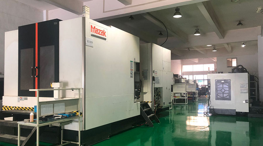 3, 4 and 5-axis precision CNC machining services for aluminum machining, beryllium, carbon steel, magnesium, titanium machining, Inconel, platinum, superalloy, acetal, polycarbonate, fiberglass, graphite and wood. Capable of machining parts up to 98 in. turning dia. and +/-0.001 in. straightness tolerance. Processes include milling, turning, drilling, boring, threading, tapping, forming, knurling, counterboring, countersinking, reaming and laser cutting. Secondary services such as assembly, centerless grinding, heat treating, plating and welding. Prototype and low to high volume production offered with maximum 50,000 units. Suitable for fluid power, pneumatics, hydraulics and valve applications. Serves the aerospace, aircraft, military, medical and defense industries.PTJ will strategize with you to provide the most cost-effective services to help you reach your target,Welcome to Contact us ( [email protected] ) directly for your new project.
- 5 Axis Machining
- Cnc Milling
- Cnc Turning
- Machining Industries
- Machining Process
- Surface Treatment
- Metal Machining
- Plastic Machining
- Powder Metallurgy Mold
- Die Casting
- Parts Gallery
- Auto Metal Parts
- Machinery Parts
- LED Heatsink
- Building Parts
- Mobile Parts
- Medical Parts
- Electronic Parts
- Tailored Machining
- Bicycle Parts
- Aluminum Machining
- Titanium Machining
- Stainless Steel Machining
- Copper Machining
- Brass Machining
- Super Alloy Machining
- Peek Machining
- UHMW Machining
- Unilate Machining
- PA6 Machining
- PPS Machining
- Teflon Machining
- Inconel Machining
- Tool Steel Machining
- More Material

