Floating Pressure Mechanism in Workpiece Clamping for Machining

In the realm of precision manufacturing, particularly in machining processes such as milling, turning, and grinding, the secure and accurate clamping of workpieces is paramount to achieving high-quality outcomes. Traditional clamping methods, such as mechanical vises or hydraulic clamps, often apply rigid forces that can induce deformation in delicate or thin-walled workpieces, leading to dimensional inaccuracies and compromised surface finishes. To address these challenges, advanced clamping technologies have emerged, among which the floating pressure mechanism stands out as a sophisticated solution. This mechanism, often referred to as floating clamping, employs adaptive force application to minimize workpiece deformation while maintaining stability during machining. By dynamically adjusting the clamping action based on the workpiece’s response to machining forces, floating pressure mechanisms enhance machining precision, particularly for complex and large-scale components used in industries such as aerospace, automotive, and medical device manufacturing.
The floating pressure mechanism is rooted in the principle of maintaining a workpiece in a low-stress state during machining. Unlike conventional clamping systems that apply a constant force, floating clamping systems use multiple clamping units to suspend the workpiece above the worktable, allowing for controlled release or adjustment of clamping forces in response to machining-induced stresses. This adaptive approach mitigates the risk of deformation, especially in thin-walled or flexible workpieces, where rigidity decreases as material is removed. The mechanism’s ability to regulate clamping action based on real-time conditions has made it a critical innovation in modern machining, particularly for components with high material removal rates, such as aircraft structural parts.
This article provides a comprehensive exploration of the floating pressure mechanism, delving into its historical development, theoretical foundations, design principles, and practical applications. It examines the scientific underpinnings of the mechanism, including the use of finite element method (FEM) analysis and strain energy evolution, and compares its performance with other clamping technologies through detailed tables. The discussion is structured to offer a rigorous, scientific perspective, drawing on recent research and industry practices to elucidate the mechanism’s role in advancing machining quality and efficiency.
Historical Context and Evolution of Clamping Technologies
The evolution of workpiece clamping technologies reflects the broader advancements in manufacturing processes over the past century. Early machining relied on manual clamps, such as screw-based vises, which required operators to apply clamping forces based on experience or intuition. While effective for simple geometries, these methods were prone to inconsistencies, particularly when machining complex or delicate parts. The introduction of hydraulic and pneumatic clamping systems in the mid-20th century marked a significant leap forward, enabling higher clamping forces and automation. However, these systems often applied excessive or uneven forces, leading to workpiece distortion, especially in thin-walled components.
The need for precision in industries like aerospace, where large-scale aluminum alloy parts with thin walls became prevalent, spurred the development of adaptive clamping technologies. By the late 20th century, researchers began exploring methods to dynamically adjust clamping forces in response to machining conditions. The concept of floating clamping emerged as a response to the limitations of rigid clamping systems, particularly for workpieces with material removal rates exceeding 90%. Initial implementations of floating clamping involved simple mechanical systems that allowed limited movement of clamping units, but these lacked precise control.
The advent of computer-aided design (CAD) and finite element analysis (FEA) in the 1980s and 1990s revolutionized the design of clamping systems. Researchers could now model the interaction between workpieces and fixtures under various machining conditions, leading to the development of sophisticated floating pressure mechanisms. These systems incorporated sensors, actuators, and control algorithms to monitor and adjust clamping forces in real time, paving the way for their widespread adoption in high-precision machining. Today, floating pressure mechanisms are integral to advanced manufacturing, supported by innovations in sensor technology, automation, and materials science.
Theoretical Foundations of Floating Pressure Mechanisms
Strain Energy Evolution and Deformation Control
The floating pressure mechanism is grounded in the principle of strain energy evolution, which describes how energy is stored andස්බිබිෂ්ටි: strain energy is a measure of the elastic energy stored in a deformed material, and its evolution during machining reflects the changes in stress and deformation as material is removed. In machining, particularly for thin-walled workpieces, the removal of material reduces the workpiece’s rigidity, increasing its susceptibility to deformation under clamping and cutting forces. The floating pressure mechanism seeks to minimize this deformation by maintaining the workpiece in a state of low stress potential energy.
Research utilizing the finite element method (FEM) has shown that the increment of deformation and the variation in strain energy between adjacent layers of removed material exhibit similar trends. When material is removed layer by layer, as in milling, the strain energy gradient—the rate of change in strain energy—can become excessive, leading to significant deformation. By loosening clamping forces at critical stages, such as when the strain energy gradient is high, the floating pressure mechanism reduces the final deformation of the workpiece. This approach, known as strain energy evolution gradient regulation, forms the basis of modern floating clamping strategies.
Finite Element Method (FEM) Analysis
The FEM is a computational technique used to simulate the behavior of workpieces under various loading conditions, including clamping and cutting forces. In the context of floating pressure mechanisms, FEM analysis is employed to model the stress distribution, deformation, and strain energy evolution during machining. For example, studies on thin-walled beams made of 7050-T7401 aluminum alloy—a common material in aerospace applications—have used FEM to analyze the layer-by-layer milling process. The workpiece is modeled as a series of layers, with each layer’s removal altering the stress field and rigidity. By inputting initial residual stress fields, obtained through experimental measurements, FEM simulations can predict deformation patterns and guide the adjustment of clamping forces.
The FEM enables researchers to identify critical points in the machining process where clamping forces should be relaxed to minimize deformation. For instance, simulations may reveal that loosening clamps during the removal of specific layers reduces the strain energy gradient, thereby decreasing the final deformation. This predictive capability is essential for designing floating pressure mechanisms that adapt to the dynamic conditions of machining.
Control Strategies for Floating Clamping
Effective control of the floating pressure mechanism requires sophisticated strategies to regulate clamping forces in real time. One common approach is the use of proportional integral (PI) controllers, which adjust clamping forces based on feedback from sensors monitoring workpiece deformation or force interactions. Bakker et al. demonstrated the use of PI controllers to adaptively adjust clamping forces in response to changes in the force between the workpiece and fixture, thereby controlling deformation in flexible workpieces.
Another approach involves responsive fixtures, which adjust the position of clamping units based on real-time deformation measurements. Li et al. proposed an adaptive machining method that integrates online measurement systems with responsive fixtures, allowing for precise control of clamping actions. These control strategies rely on advanced sensor systems, such as strain gauges or piezoelectric sensors, to provide accurate data on clamping and cutting forces, enabling dynamic adjustments that maintain workpiece stability without inducing excessive stress.
Design Principles of Floating Pressure Mechanisms
Components of Floating Clamping Systems
A floating pressure mechanism typically consists of multiple clamping units, a control system, and a support structure. The clamping units, often hydraulic or pneumatic actuators, are designed to apply controlled forces to the workpiece, suspending it above the worktable. Each unit is independently adjustable, allowing for localized force application that adapts to the workpiece’s geometry and machining conditions. The control system integrates sensors, such as strain gauges or piezoelectric sensors, with actuators and a feedback loop to monitor and adjust clamping forces in real time. The support structure, often a rigid frame or fixture, ensures stability while allowing the clamping units to move freely within defined constraints.
Sensor Integration and Real-Time Monitoring
Sensor technology is critical to the functionality of floating pressure mechanisms. Strain gauges embedded in clamping jaws or fixtures measure static clamping forces, while piezoelectric sensors, such as those made of lead zirconate titanate (PZT), capture dynamic forces induced by cutting operations. These sensors provide real-time data on the interaction between the workpiece and fixture, enabling the control system to detect changes in clamping force or vibrations that could compromise machining quality.
For example, the iJaw system developed by Röhm incorporates integrated sensor technology within clamping jaws to measure clamping forces directly at the clamping point. The system uses wireless IO-Link protocols to transmit data at a sampling rate of 100 Hz, allowing for real-time monitoring during machining. Such advancements in sensor integration enhance the precision and reliability of floating pressure mechanisms, particularly for thin-walled or sensitive workpieces.
Actuation Mechanisms
The actuation mechanisms in floating pressure systems are typically hydraulic, pneumatic, or electromechanical. Hydraulic actuators are favored for their ability to deliver high clamping forces and rapid pressure buildup, making them suitable for challenging workpiece shapes. Pneumatic actuators, while offering quicker response times, are limited by lower operating pressures and potential rebound effects under overload conditions. Electromechanical actuators, driven by servo motors, provide precise control and are increasingly used in automated systems. The choice of actuation mechanism depends on the specific requirements of the machining process, including the workpiece material, geometry, and desired clamping force.
Applications in Machining
Aerospace Manufacturing
The aerospace industry is a primary beneficiary of floating pressure mechanisms due to the prevalence of large-scale, thin-walled aluminum alloy components, such as aircraft beams and fuselage panels. These components, often made of 7050-T7401 or 7075-T7401 aluminum alloys, have material removal rates exceeding 90%, making them highly susceptible to deformation. Floating clamping systems, by adaptively releasing deformation during milling, significantly improve machining quality. For instance, FEM-based studies on thin-walled beams have demonstrated that targeted clamping loosening reduces final deformation, ensuring compliance with stringent aerospace tolerances.
Automotive and Medical Device Manufacturing
In the automotive industry, floating pressure mechanisms are used to machine lightweight components, such as aluminum chassis parts, where precision and weight reduction are critical. Similarly, in medical device manufacturing, floating clamping is employed to produce intricate components, such as titanium implants, where deformation could compromise biocompatibility or functionality. The ability to maintain low stress states during machining ensures that these components meet exacting standards for dimensional accuracy and surface finish.
Composite Materials and Additive Manufacturing
The increasing use of composite materials, such as carbon fiber-reinforced polymers (CFRP), and additive manufacturing techniques has expanded the application of floating pressure mechanisms. Composites, with their anisotropic properties, are prone to delamination and deformation under rigid clamping. Floating clamping systems, by applying controlled forces, minimize these risks. In additive manufacturing, where machined surfaces often require post-processing, floating pressure mechanisms ensure stability without distorting the delicate structures produced by 3D printing.
Comparison with Other Clamping Technologies
To evaluate the effectiveness of floating pressure mechanisms, it is useful to compare them with other clamping technologies, including mechanical vises, hydraulic clamps, pneumatic clamps, magnetic clamps, and vacuum clamps. Each method has distinct advantages and limitations, which are summarized in the following tables.
Table 1: Comparison of Clamping Technologies
|
Clamping Technology |
Clamping Force |
Response Time |
Suitability for Thin-Walled Parts |
Automation Level |
Maintenance Requirements |
|---|---|---|---|---|---|
|
Floating Pressure Mechanism |
Adjustable, adaptive |
Fast (real-time) |
High |
High (sensor-based) |
Moderate |
|
Mechanical Vise |
High, fixed |
Slow (manual) |
Low |
Low |
Low |
|
Hydraulic Clamp |
High, uniform |
Moderate |
Moderate |
High |
High |
|
Pneumatic Clamp |
Low to moderate |
Fast |
Low |
High |
Moderate |
|
Magnetic Clamp |
High, concentrated |
Fast |
Moderate |
Moderate |
Low |
|
Vacuum Clamp |
Low to moderate |
Moderate |
High (for flat surfaces) |
Moderate |
Moderate |
Notes:
-
Clamping Force: Floating pressure mechanisms offer adjustable forces, making them ideal for dynamic conditions. Mechanical vises provide high but fixed forces, which can deform thin-walled parts.
-
Response Time: Floating systems and pneumatic clamps respond quickly, while mechanical vises are slower due to manual operation.
-
Suitability for Thin-Walled Parts: Floating mechanisms and vacuum clamps excel with delicate parts, while mechanical vises and pneumatic clamps are less suitable.
-
Automation Level: Floating and hydraulic systems support high automation, whereas mechanical vises are typically manual.
-
Maintenance Requirements: Hydraulic systems require more maintenance due to fluid management, while mechanical and magnetic systems are simpler.
Table 2: Performance Metrics for Clamping Technologies
|
Clamping Technology |
Deformation Control |
Precision |
Setup Time |
Cost |
Applications |
|---|---|---|---|---|---|
|
Floating Pressure Mechanism |
Excellent |
High |
Moderate |
High |
Aerospace, medical devices |
|
Mechanical Vise |
Poor |
Moderate |
High |
Low |
General machining |
|
Hydraulic Clamp |
Good |
High |
Moderate |
Moderate |
Automotive, aerospace |
|
Pneumatic Clamp |
Poor |
Moderate |
Low |
Moderate |
Small batch production |
|
Magnetic Clamp |
Good |
High |
Low |
High |
Milling, grinding |
|
Vacuum Clamp |
Good |
Moderate |
Moderate |
Moderate |
Wood, composites |
Notes:
-
Deformation Control: Floating mechanisms provide superior deformation control due to adaptive force application.
-
Precision: Floating, hydraulic, and magnetic clamps offer high precision, suitable for tight tolerances.
-
Setup Time: Pneumatic and magnetic clamps require less setup time, while mechanical vises are time-intensive.
-
Cost: Floating and magnetic systems are more expensive due to advanced technology.
-
Applications: Floating mechanisms are specialized for high-precision industries, while mechanical vises are versatile for general use.
Recent Advances and Future Directions
Sensor and IoT Integration
Recent advances in sensor technology and the Internet of Things (IoT) have enhanced the capabilities of floating pressure mechanisms. Systems like the iJaw demonstrate the potential of wireless sensor networks to monitor clamping forces in real time, enabling predictive maintenance and process optimization. The integration of IoT protocols, such as IO-Link Wireless, allows for seamless communication between clamping systems and machine tools, facilitating fully automated production environments.
Machine Learning and Predictive Modeling
Machine learning algorithms are increasingly being applied to predict deformation patterns and optimize clamping strategies. By analyzing historical machining data and FEM simulations, these algorithms can identify optimal clamping force profiles for specific workpieces, reducing trial-and-error in fixture design. Neural network-based models, as demonstrated in studies on turning processes, achieve high prediction accuracy for quality parameters like roughness and roundness, suggesting potential applications in floating clamping control.
Hybrid Clamping Systems
A growing trend is the development of hybrid clamping systems that combine floating pressure mechanisms with other technologies, such as zero-point clamping or magnetic clamping. These systems offer flexibility and modularity, allowing manufacturers to adapt to diverse workpiece geometries and production requirements. For example, zero-point clamping towers integrated with floating units enable rapid setup changes while maintaining adaptive force control.
Sustainability and Energy Efficiency
As manufacturing industries prioritize sustainability, floating pressure mechanisms are being designed with energy efficiency in mind. Electromechanical actuators, which consume less energy than hydraulic systems, are gaining traction. Additionally, optimized clamping strategies that minimize deformation reduce material waste, contributing to more sustainable production processes.
Challenges and Limitations
Despite their advantages, floating pressure mechanisms face several challenges. The complexity of sensor-based control systems increases design and maintenance costs, making them less accessible for small-scale manufacturers. The reliance on accurate FEM models requires precise input data, such as residual stress fields, which can be difficult to measure experimentally. Furthermore, the integration of floating clamping with existing machine tools may require significant retrofitting, posing logistical challenges.
Another limitation is the potential for reduced clamping force in highly dynamic machining conditions, such as high-speed milling, where vibrations can destabilize the workpiece. Advanced damping systems, such as those using piezo-stack actuators, are being explored to address this issue, but their implementation adds further complexity and cost.
Case Studies
Case Study 1: Aerospace Beam Machining
A study on the machining of 7050-T7401 aluminum alloy beams for aircraft wings utilized a floating pressure mechanism to control deformation during layer-by-layer milling. FEM analysis revealed that loosening clamping forces at specific layers reduced the strain energy gradient, resulting in a 30% decrease in final deformation compared to traditional hydraulic clamping. The system employed hydraulic actuators and strain gauges, with a PI controller adjusting forces based on real-time feedback. The results underscored the mechanism’s efficacy for large-scale, thin-walled components.
Case Study 2: CFRP Drilling
In the drilling of carbon fiber-reinforced polymer (CFRP) panels for aerospace applications, a floating pressure mechanism was used to prevent delamination. The system incorporated pneumatic actuators and piezoelectric sensors to monitor clamping forces, with a responsive fixture adjusting clamp positions based on deformation measurements. The approach reduced peel-up and push-out delamination by 25%, demonstrating the mechanism’s suitability for composite materials.
Conclusion
The floating pressure mechanism represents a significant advancement in workpiece clamping for machining, offering adaptive force control that minimizes deformation and enhances precision. Rooted in the principles of strain energy evolution and supported by FEM analysis, this technology addresses the challenges of machining thin-walled, complex, and high-value components. Its applications in aerospace, automotive, and medical device manufacturing highlight its versatility, while recent advances in sensor technology, machine learning, and hybrid systems point to a promising future.
However, the complexity and cost of floating pressure mechanisms pose barriers to widespread adoption, particularly for smaller manufacturers. Ongoing research aims to address these challenges through energy-efficient designs, simplified control systems, and improved integration with existing machinery. As manufacturing continues to evolve toward automation and sustainability, the floating pressure mechanism will play a pivotal role in achieving the precision and efficiency demanded by modern industries.
Reprint Statement: If there are no special instructions, all articles on this site are original. Please indicate the source for reprinting:https://www.cncmachiningptj.com/,thanks!
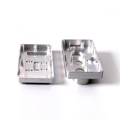
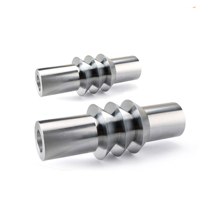
 3, 4 and 5-axis precision CNC machining services for aluminum machining, beryllium, carbon steel, magnesium, titanium machining, Inconel, platinum, superalloy, acetal, polycarbonate, fiberglass, graphite and wood. Capable of machining parts up to 98 in. turning dia. and +/-0.001 in. straightness tolerance. Processes include milling, turning, drilling, boring, threading, tapping, forming, knurling, counterboring, countersinking, reaming and laser cutting. Secondary services such as assembly, centerless grinding, heat treating, plating and welding. Prototype and low to high volume production offered with maximum 50,000 units. Suitable for fluid power, pneumatics, hydraulics and valve applications. Serves the aerospace, aircraft, military, medical and defense industries.PTJ will strategize with you to provide the most cost-effective services to help you reach your target,Welcome to Contact us ( [email protected] ) directly for your new project.

- 5 Axis Machining
- Cnc Milling
- Cnc Turning
- Machining Industries
- Machining Process
- Surface Treatment
- Metal Machining
- Plastic Machining
- Powder Metallurgy Mold
- Die Casting
- Parts Gallery
- Auto Metal Parts
- Machinery Parts
- LED Heatsink
- Building Parts
- Mobile Parts
- Medical Parts
- Electronic Parts
- Tailored Machining
- Bicycle Parts
- Aluminum Machining
- Titanium Machining
- Stainless Steel Machining
- Copper Machining
- Brass Machining
- Super Alloy Machining
- Peek Machining
- UHMW Machining
- Unilate Machining
- PA6 Machining
- PPS Machining
- Teflon Machining
- Inconel Machining
- Tool Steel Machining
- More Material